
Article Categories
- All Categories
-
 Data Structure
-
 Networking
-
 RDBMS
RDBMS
-
 Operating System
-
 Java
Java
-
 MS Excel
-
 iOS
iOS
-
 HTML
HTML
-
 CSS
CSS
-
 Android
-
 Python
-
 C Programming
-
 C++
C++
-
 C#
C#
-
 MongoDB
-
 MySQL
MySQL
-
 Javascript
-
 PHP
PHP
-
 Economics & Finance
Things Needed to start IOT
IOT ie. The Internet of Things refers to all those devices that can communicate over the Internet and can be made accessible or connectable by anybody and from anywhere in the world. IoT is already being used or has been seen implemented in different forms such as in Smart cars and watches, Smart homes, Smart irrigation systems, Smart cities, etc.
To start learning IOT, first, it is important to learn about the things that are needed to make circuits. There are some simulators available to make the beginner of IOT learn these concepts without even having the IOT devices available. However to get real results, knowing about the circuit components and making the actual circuit is important. In this article, using two different approaches, the things needed to start IOT programming are given. In approach 1, the online simulators as the requirement for virtual circuit making are discussed and in approach 2, the things needed for making the actual circuits are discussed along with the required software to control this actual circuit.
Multiple Approaches
Approach 1 ? Requirements for starting IOT using Virtual Circuits.
Approach 2 ? Requirements for starting IOT and making actual circuits.
Approach 1: Requirements for starting IOT using Virtual Circuits.
Softwares are available for designing virtual circuits. For example, Cisco packet tracer, Tinkercad, and Wokwi, etc.
Cisco packet tracer
Here the settings of different IOT components and devices can be learned easily while connecting the devices to layout the IOT conceptual diagram.
Tinkercad
Tincarcad can be used to understand the connections of IOT components as well as other electrical circuit designs.
Wokwi
Wokwi is a very useful simulation software where the code can be written, the virtual colorful diagram can be made and the results can be seen easily. Even the libraries or modules that are needed for the code can be linked if available and otherwise these can be uploaded. One can save, share and transfer the code file, the diagram of the circuit as well as the whole project easily.
It is an easy-to-use and free service to start with learning IOT. The wokwi link is given here.
Circuit Design Steps and Coding using Simulator
Step 1 ? Choose the right IOT simulation software, for example, Wokwi.
Step 2 ? Make a virtual circuit. Choose the microcontroller such as ESP32 and components.
Step 3 ? Attach the wires and make the connections with the correct microcontroller pins and pins of the components /sensors used.
Step 4 ? Use a programming language such as C to write the program.
Step 5 ? Link the libraries and the modules.
Step 6 ? Start the simulation and compile the program.
Step 7 ? Check the results.
Exploring the Wokwi Simulator - Approach 1:
After login into wokwi, first make the circuit in the right side area and write the code using C language in the left side code area. The microcontroller needed for the project can be chosen.

Fig 1: Choosing the microcontroller from the list for an IOT project on Wokwi
Approach 2: Requirements for starting IOT and making actual circuits
There are a lot of options to buy these IOT kits, how ever we prefer making an IOT kit for beginners having only the components as described in this lesson. Other component's usage can be first understood virtually using some online software such as wokwi and later can be bought on need.
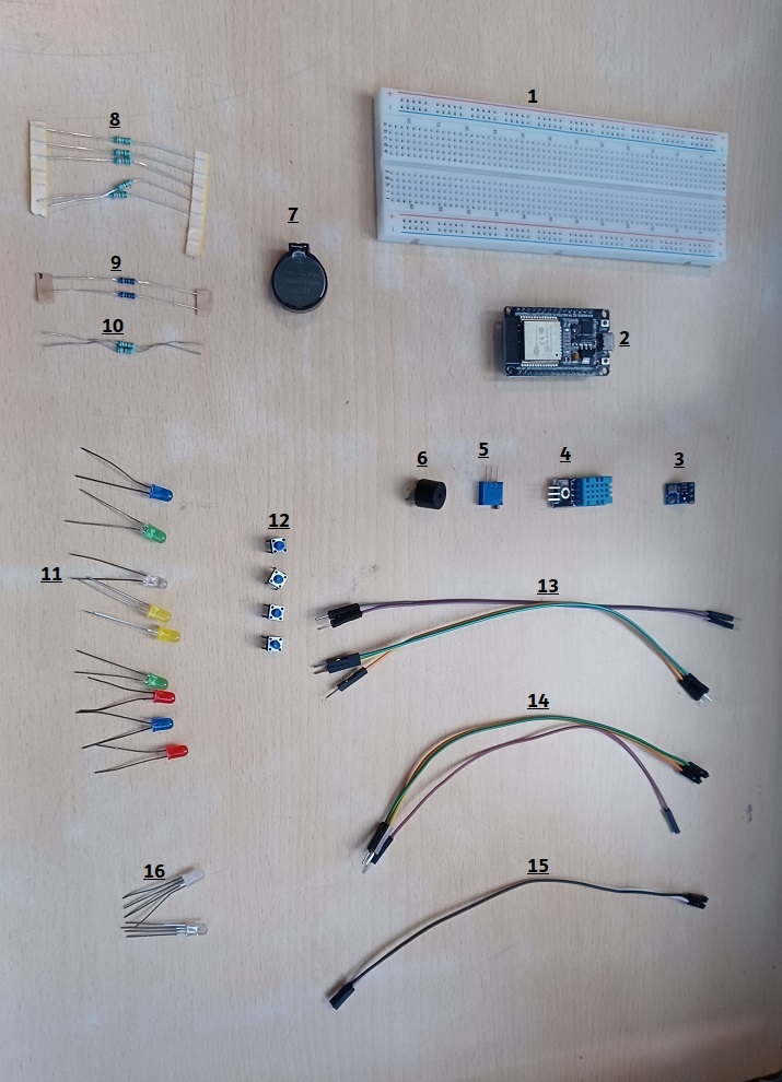
Fig 2: Basic components for IOT Circuit Designing
The details are given below. The components, especially the resistors and wires shown in the figure are just for reference and may not match the details.
A breadboard to connect the IoT components, wires, and sensors: A high-quality MB102 830 Points Solderless Prototype PCB
A microcontroller for designing IOT solutions: ESP32Wroom32 kit with the 30-pin layout.
Sensors: BMP sensor
Sensors: DTH sensor
Potentiometer
1 x 3v Buzzer 12mm
Coin battery and Holder
Resistors: 10 Resistors ( 1K )
Resistors: 2 Resistors ( 330 Ohm )
Resistors: 2 Resistors ( 10K )
LEDs to be used as output devices: 5 to 10 different color LEDs (5mm)
PushButtons: 5 pushbuttons
20 x Jumper Wires Male - Male 20cm
5 x Jumper Wires Male - Female 20cm
5 x Jumper Wires Female - Female 20cm
RGB LEDs: 1 RGB LED Common Anode 4 Pin (5mm)
Wire to connect the microcontroller to the computer: A USB data cable
Arduino Software to run the code.
Actual Circuit Design Steps and Coding
Step 1 ? Connect the ESP32 microcontroller on the breadboard.
Step 2 ? Choose the components from the IOT kit and connect these to the breadboard.
Step 3 ? Make the wire connections.
Step 4 ? Start Arduino IDE. Write the C program and compile it using the tick sign.
Step 5 ? Upload the program to ESP32 by pressing the right arrow near the tick sign. Check the results on the circuit.
Viewing The Result
Once the things are collected the following type of circuits are made.
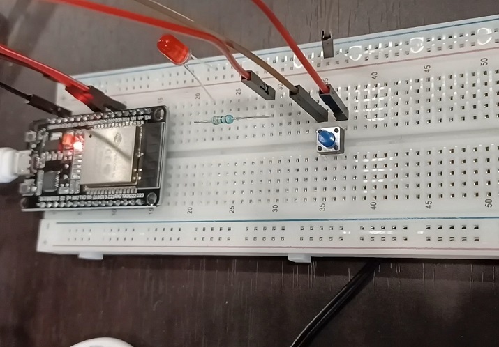
Fig 3: An example circuit made with things from the IOT learning kit.
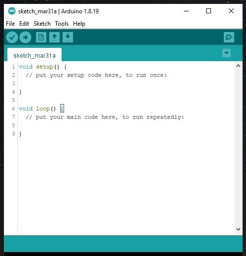
Fig 3: The software needed for writing the program using C, to control the IOT circuit.
To start the IOT and to begin learning these types of automation, either some online simulation software can be used or a basic IOT kit can be purchased. Here, using two different approaches, the things needed to start IOT lessons are given. In Approach 1, Using IOT Simulation software for making virtual circuits is given and in Approach 2, the things needed for making actual circuits are discussed and presented.

359 Views
