- Python Penetration Testing - Home
- Introduction
- Assessment Methodology
- Primer on Network Communication
- The Socket and its Methods
- Python Network Scanner
- Network Packet Sniffing
- ARP Spoofing
- Pentesting of Wireless Network
- Application Layer
- Client-side Validation
- DoS & DDoS attack
- SQLi Web Attack
- XSS Web Attack
- Useful Resources
- Quick Guide
- Useful Resources
- Discussion
A Primer on Network Communication
We have always heard that to perform penetration testing, a pentester must be aware about basic networking concepts like IP addresses, classful subnetting, classless subnetting, ports and broadcasting networks. The very first reason is that the activities like which hosts are live in the approved scope and what services, ports and features they have open and responsive will determine what kind of activities an assessor is going to perform in penetration testing. The environment keeps changing and systems are often reallocated. Hence, it is quite possible that old vulnerabilities may crop up again and without the good knowledge of scanning a network, it may happen that the initial scans have to be redone. In our subsequent sections, we will discuss the basics of network communication.
Reference Model
Reference Model offers a means of standardization, which is acceptable worldwide since people using the computer network are located over a wide physical range and their network devices might have heterogeneous architecture. In order to provide communication among heterogeneous devices, we need a standardized model, i.e., a reference model, which would provide us with a way these devices can communicate.
We have two reference models such as the OSI model and the TCP/IP reference model. However, the OSI model is a hypothetical one but the TCP/IP is an practical model.
OSI Model
The Open System Interface was designed by the International organization of Standardization (ISO) and therefore, it is also referred to as the ISO-OSI Model.
The OSI model consists of seven layers as shown in the following diagram. Each layer has a specific function, however each layer provides services to the layer above.
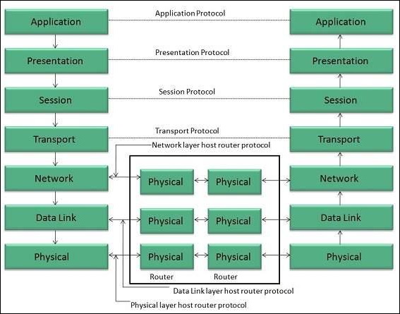
Physical Layer
The Physical layer is responsible for the following activities −
Activating, maintaining and deactivating the physical connection.
Defining voltages and data rates needed for transmission.
Converting digital bits into electrical signal.
Deciding whether the connection is simplex, half-duplex or full-duplex.
Data Link Layer
The data link layer performs the following functions −
Performs synchronization and error control for the information that is to be transmitted over the physical link.
Enables error detection, and adds error detection bits to the data that is to be transmitted.
Network Layer
The network layer performs the following functions −
To route the signals through various channels to the other end.
To act as the network controller by deciding which route data should take.
To divide the outgoing messages into packets and to assemble incoming packets into messages for higher levels.
Transport Layer
The Transport layer performs the following functions −
It decides if the data transmission should take place on parallel paths or single path.
It performs multiplexing, splitting on the data.
It breaks the data groups into smaller units so that they are handled more efficiently by the network layer.
The Transport Layer guarantees transmission of data from one end to other end.
Session Layer
The Session layer performs the following functions −
Manages the messages and synchronizes conversations between two different applications.
It controls logging on and off, user identification, billing and session management.
Presentation Layer
The Presentation layer performs the following functions −
This layer ensures that the information is delivered in such a form that the receiving system will understand and use it.
Application Layer
The Application layer performs the following functions −
It provides different services such as manipulation of information in several ways, retransferring the files of information, distributing the results, etc.
The functions such as LOGIN or password checking are also performed by the application layer.
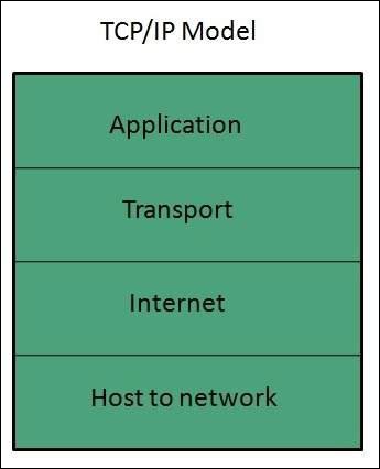
TCP/IP Model
The Transmission Control Protocol and Internet Protocol (TCP/IP) model is a practical model and is used in the Internet.
The TCP/IP model combines the two layers (Physical and Data link layer) into one layer Host-to-Network layer. The following diagram shows the various layers of TCP/IP model −
Application Layer
This layer is same as that of the OSI model and performs the following functions −
It provides different services such as manipulation of information in several ways, retransferring the files of information, distributing the results, etc.
The application layer also performs the functions such as LOGIN or password checking.
Following are the different protocols used in the Application layer −
- TELNET
- FTP
- SMTP
- DN
- HTTP
- NNTP
Transport Layer
It does the same functions as that of the transport layer in the OSI model. Consider the following important points related to the transport layer −
It uses TCP and UDP protocol for end to end transmission.
TCP is a reliable and connection oriented protocol.
TCP also handles flow control.
The UDP is not reliable and a connection less protocol does not perform flow control.
TCP/IP and UDP protocols are employed in this layer.
Internet Layer
The function of this layer is to allow the host to insert packets into network and then make them travel independently to the destination. However, the order of receiving the packet can be different from the sequence they were sent.
Internet Protocol (IP) is employed in Internet layer.
Host-to-Network Layer
This is the lowest layer in the TCP/IP model. The host has to connect to network using some protocol, so that it can send IP packets over it. This protocol varies from host to host and network to network.
The different protocols used in this layer are −
- ARPANET
- SATNET
- LAN
- Packet radio
Useful Architecture
Following are some useful architectures, which are used in network communication −
The Ethernet frame architecture
An engineer named Robert Metcalfe first invented Ethernet network, defined under IEEE standard 802.3, in 1973. It was first used to interconnect and send data between workstation and printer. More than 80% of the LANs use Ethernet standard for its speed, lower cost and ease of installation. On the other side, if we talk about frame then data travels from host to host in the way. A frame is constituted by various components like MAC address, IP header, start and end delimiter, etc.
The Ethernet frame starts with Preamble and SFD. The Ethernet header contains both Source and Destination MAC address, after which the payload of frame is present. The last field is CRC, which is used to detect the error. The basic Ethernet frame structure is defined in the IEEE 802.3 standard, which is explained as below −
The Ethernet (IEEE 802.3) frame format
The Ethernet packet transports an Ethernet frame as its payload. Following is a graphical representation of Ethernet frame along with the description of each field −
| Field Name | Preamble | SFD(Start of frame delimiter) | Destination MAC | Source MAC | Type | Data | CRC |
|---|---|---|---|---|---|---|---|
| Size(in bytes) | 7 | 1 | 6 | 6 | 2 | 46-1500 | 4 |
Preamble
An Ethernet frame is preceded by a preamble, 7 bytes of size, which informs the receiving system that a frame is starting and allows sender as well as receiver to establish bit synchronization.
SFD (Start of frame delimiter)
This is a 1-byte field used to signify that the Destination MAC address field begins with the next byte. Sometimes the SFD field is considered to be the part of Preamble. That is why preamble is considered 8 bytes in many places.
Destination MAC − This is a 6-byte field wherein, we have the address of the receiving system.
Source MAC − This is a 6-byte field wherein, we have the address of the sending system.
Type − It defines the type of protocol inside the frame. For example, IPv4 or IPv6. Its size is 2 bytes.
Data − This is also called Payload and the actual data is inserted here. Its length must be between 46-1500 bytes. If the length is less than 46 bytes then padding 0s is added to meet the minimum possible length, i.e., 46.
CRC (Cyclic Redundancy Check) − This is a 4-byte field containing 32-bit CRC, which allows detection of corrupted data.
Extended Ethernet Frame (Ethernet II frame) Format
Following is a graphical representation of the extended Ethernet frame using which we can get Payload larger than 1500 bytes −
| Field Name | Destination MAC | Source MAC | Type | DSAP | SSAP | Ctrl | Data | CRC |
|---|---|---|---|---|---|---|---|---|
| Size(in bytes) | 6 | 6 | 2 | 1 | 1 | 1 | >46 | 4 |
The description of the fields, which are different from IEEE 802.3 Ethernet frame, is as follows −
DSAP (Destination Service Access Point)
DSAP is a 1-byte long field that represents the logical addresses of the network layer entity intended to receive the message.
SSAP (Source Service Access Point)
SSAP is a 1-byte long field that represents the logical address of the network layer entity that has created the message.
Ctrl
This is a 1-byte control field.
The IP Packet Architecture
Internet Protocol is one of the major protocols in the TCP/IP protocols suite. This protocol works at the network layer of the OSI model and at the Internet layer of the TCP/IP model. Thus, this protocol has the responsibility of identifying hosts based upon their logical addresses and to route data among them over the underlying network. IP provides a mechanism to uniquely identify hosts by an IP addressing scheme. IP uses best effort delivery, i.e., it does not guarantee that packets would be delivered to the destined host, but it will do its best to reach the destination.
In our subsequent sections, we will learn about the two different versions of IP.
IPv4
This is the Internet Protocol version 4, which uses 32-bit logical address. Following is the diagram of IPv4 header along with the description of fields −
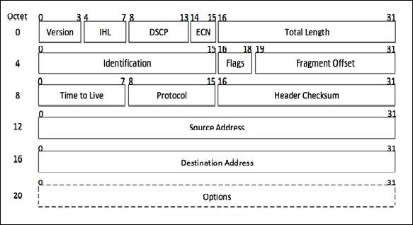
Version
This is the version of the Internet Protocol used; for example, IPv4.
IHL
Internet Header Length; length of the entire IP header.
DSCP
Differentiated Services Code Point; this is the Type of Service.
ECN
Explicit Congestion Notification; it carries information about the congestion seen in the route.
Total Length
The length of the entire IP Packet (including IP header and IP Payload).
Identification
If the IP packet is fragmented during the transmission, all the fragments contain the same identification number.
Flags
As required by the network resources, if the IP Packet is too large to handle, these flags tell if they can be fragmented or not. In this 3-bit flag, the MSB is always set to 0.
Fragment Offset
This offset tells the exact position of the fragment in the original IP Packet.
Time to Live
To avoid looping in the network, every packet is sent with some TTL value set, which tells the network how many routers (hops) this packet can cross. At each hop, its value is decremented by one and when the value reaches zero, the packet is discarded.
Protocol
Tells the Network layer at the destination host, to which Protocol this packet belongs, i.e., the next level Protocol. For example, the protocol number of ICMP is 1, TCP is 6 and UDP is 17.
Header Checksum
This field is used to keep checksum value of entire header, which is then used to check if the packet is received error-free.
Source Address
32-bit address of the Sender (or source) of the packet.
Destination Address
32-bit address of the Receiver (or destination) of the packet.
Options
This is an optional field, which is used if the value of IHL is greater than 5. These options may contain values for options such as Security, Record Route, Time Stamp, etc.
If you want to study IPv4 in detail, please refer to this link - www.tutorialspoint.com/ipv4/index.htm
IPv6
The Internet Protocol version 6 is the most recent communications protocol, which as its predecessor IPv4 works on the Network Layer (Layer-3). Along with its offering of an enormous amount of logical address space, this protocol has ample features , which address the shortcoming of IPv4. Following is the diagram of IPv4 header along with the description of fields −
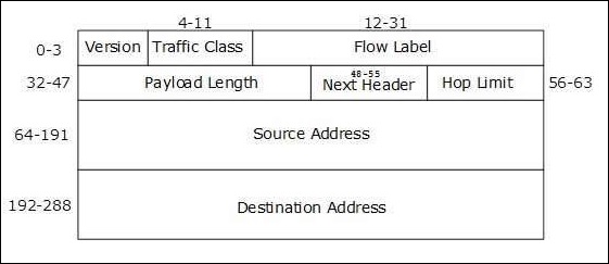
Version (4-bits)
It represents the version of Internet Protocol 0110.
Traffic Class (8-bits)
These 8 bits are divided into two parts. The most significant 6 bits are used for the Type of Service to let the Router Known what services should be provided to this packet. The least significant 2 bits are used for Explicit Congestion Notification (ECN).
Flow Label (20-bits)
This label is used to maintain the sequential flow of the packets belonging to a communication. The source labels the sequence to help the router identify that a particular packet belongs to a specific flow of information. This field helps avoid re-ordering of data packets. It is designed for streaming/real-time media.
Payload Length (16-bits)
This field is used to tell the routers how much information a particular packet contains in its payload. Payload is composed of Extension Headers and Upper Layer data. With 16 bits, up to 65535 bytes can be indicated; but if the Extension Headers contain Hop-by-Hop Extension Header, then the payload may exceed 65535 bytes and this field is set to 0.
Next Header (8-bits)
Either this field is used to indicate the type of Extension Header, or if the Extension Header is not present then it indicates the Upper Layer PDU. The values for the type of Upper Layer PDU are same as IPv4s.
Hop Limit (8-bits)
This field is used to stop packet to loop in the network infinitely. This is same as TTL in IPv4. The value of Hop Limit field is decremented by 1 as it passes a link (router/hop). When the field reaches 0, the packet is discarded.
Source Address (128-bits)
This field indicates the address of originator of the packet.
Destination Address (128-bits)
This field provides the address of the intended recipient of the packet.
If you want to study IPv6 in detail, please refer to this link www.tutorialspoint.com/ipv6/index.htm
The TCP (Transmission Control Protocol) Header Architecture
As we know that TCP is a connection-oriented protocol, in which a session is established between two systems before starting communication. The connection would be closed once the communication has been completed. TCP uses a three-way handshake technique for establishing the connection socket between two systems. Three-way handshake means that three messages SYN, SYN-ACK and ACK, are sent back and forth between two systems. The steps of working between two systems, initiating and target systems, are as follows −
Step 1 − Packet with SYN flag set
First of all the system that is trying to initiate a connection starts with a packet that has the SYN flag set.
Step 2 − Packet with SYN-ACK flag set
Now, in this step the target system returns a packet with SYN and ACK flag sets.
Step 3 − Packet with ACK flag set
At last, the initiating system will return a packet to the original target system with ACK flag set.
Following is the diagram of the TCP header along with the description of fields −
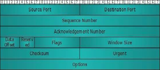
Source Port (16-bits)
It identifies the source port of the application process on the sending device.
Destination Port (16-bits)
It identifies the destination port of the application process on the receiving device.
Sequence Number (32-bits)
The sequence number of data bytes of a segment in a session.
Acknowledgement Number (32-bits)
When ACK flag is set, this number contains the next sequence number of the data byte expected and works as an acknowledgment of the previous data received.
Data Offset (4-bits)
This field implies both, the size of the TCP header (32-bit words) and the offset of data in the current packet in the whole TCP segment.
Reserved (3-bits)
Reserved for future use and set to zero by default.
Flags (1-bit each)
NS − Explicit Congestion Notification signaling process uses this Nonce Sum bit.
CWR − When a host receives packet with ECE bit set, it sets Congestion Windows Reduced to acknowledge that ECE received.
ECE − It has two meanings −
If SYN bit is clear to 0, then ECE means that the IP packet has its CE (congestion experience) bit set.
If SYN bit is set to 1, ECE means that the device is ECT capable.
URG − It indicates that Urgent Pointer field has significant data and should be processed.
ACK − It indicates that Acknowledgement field has significance. If ACK is cleared to 0, it indicates that packet does not contain any acknowledgment.
PSH − When set, it is a request to the receiving station to PUSH data (as soon as it comes) to the receiving application without buffering it.
RST − Reset flag has the following features −
It is used to refuse an incoming connection.
It is used to reject a segment.
It is used to restart a connection.
SYN − This flag is used to set up a connection between hosts.
FIN − This flag is used to release a connection and no more data is exchanged thereafter. Because packets with SYN and FIN flags have sequence numbers, they are processed in correct order.
Windows Size
This field is used for flow control between two stations and indicates the amount of buffer (in bytes) the receiver has allocated for a segment, i.e., how much data is the receiver expecting.
Checksum − This field contains the checksum of Header, Data and Pseudo Headers.
Urgent Pointer − It points to the urgent data byte if URG flag is set to 1.
Options − It facilitates additional options, which are not covered by the regular header. Option field is always described in 32-bit words. If this field contains data less than 32-bit, padding is used to cover the remaining bits to reach 32-bit boundary.
If you want to study TCP in detail, please refer to this link https://www.tutorialspoint.com/data_communication_computer_network/transmission_control_protocol.htm
The UDP (User Datagram Protocol) header architecture
UDP is a simple connectionless protocol unlike TCP, a connection-oriented protocol. It involves minimum amount of communication mechanism. In UDP, the receiver does not generate an acknowledgment of packet received and in turn, the sender does not wait for any acknowledgment of the packet sent. This shortcoming makes this protocol unreliable as well as easier on processing. Following is the diagram of the UDP header along with the description of fields −
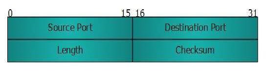
Source Port
This 16-bits information is used to identify the source port of the packet.
Destination Port
This 16-bits information is used to identify the application level service on the destination machine.
Length
The length field specifies the entire length of the UDP packet (including header). It is a 16-bits field and the minimum value is 8-byte, i.e., the size of the UDP header itself.
Checksum
This field stores the checksum value generated by the sender before sending. IPv4 has this field as optional so when checksum field does not contain any value, it is made 0 and all its bits are set to zero.
To study TCP in detail, please refer to this link User Datagram Protocol
