- Optical Networks - Home
- Optical Networks - Introduction
- Convergence Networks
- Optical Data Networking
- Optical Devices
- Single and Multi-hop Networks
- Optical Networks - WDM Technology
- Optical Networks - ROADM
Optical Networks - WDM Technology
WDM is a technology that enables various optical signals to be transmitted by a single fiber. Its principle is essentially the same as Frequency Division Multiplexing (FDM). That is, several signals are transmitted using different carriers, occupying non-overlapping parts of a frequency spectrum. In case of WDM, the spectrum band used is in the region of 1300 or 1550 nm, which are two wavelength windows at which optical fibers have very low signal loss.
Initially, each window was used to transmit a single digital signal. With the advance of optical components, such as Distributed Feedback (DFB) lasers, Erbium-doped Fiber Amplifiers (EDFAs), and photo-detectors, it was soon realized that each transmitting window could in fact be used by several optical signals, each occupying a small traction of the total wavelength window available.
In fact, the number of optical signals multiplexed within a window is limited only by the precision of these components. With the current technology, over 100 optical channels can be multiplexed into a single fiber. The technology was then named dense WDM (DWDM).
WDM in the Long Haul
In 1995, long-haul carriers in the United States started deploying point-to-point WDM transmission systems to upgrade the capacity of their networks while leveraging their existing fiber infrastructures. Since then, WDM has also taken the long-haul market by storm. WDM technology allows to cope with ever-increasing capacity requirements while postponing the exhaustion of fiber and increasing the flexibility for capacity upgrade.
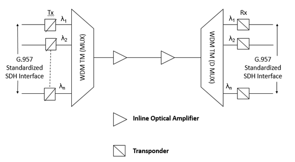
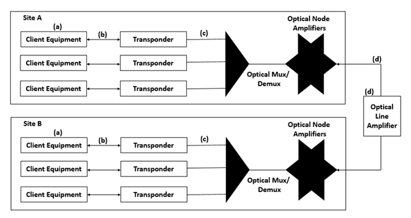
The most prevailing driver, however, is the cost advantage of the WDM solution compared to competing solutions, such as Space Division Multiplexing (SDM) or enhanced Time Division Multiplexing (TDM) to upgrade the network capacity. The "open" WDM solution, illustrated in the following figure makes use of transponders in WDM terminal multiplexers (TMs) and inline optical amplifiers that are shared by multiple wavelength channels.
The transponder is in essence a 3R opto-electro-optic (O/E/O) converter, that converts a G.957 standard compliant optical signal into an appropriate wavelength channel (and vice versa) while repowering, reshaping and retiming the signal electrically. The SDM solution uses multiple fiber pairs in parallel, each equipped with SDH regenerators instead of multiple wavelengths sharing the same inline optical amplifier. Upgrading to higher TDM rates (e.g., from 2.5 Gb/s STM-16 to 10 Gb/s STM-64) is only a short-lived solution since transmission impairments such as dispersion do not scale well with increasing TDM rates, especially on standard single-mode fiber.
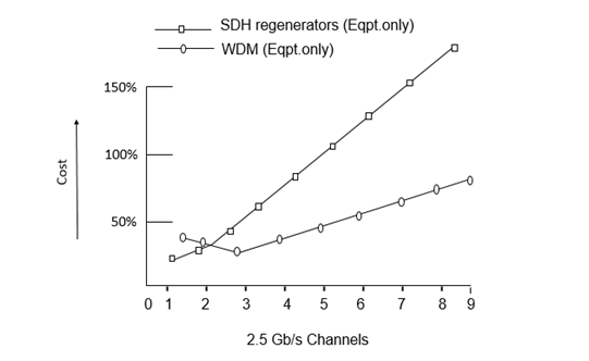
A case study has demonstrated that long haul point-to-point WDM systems are clearly a more cost-effective solution than SDM, even for as low as three channels of STM-16. The above figure illustrates two link cost comparisons for the initial core of a transport network consisting of 5000 fiber km with an average distance of 300 kms between two access cities. Note that the 100 percent cost reference point in the above figure corresponds to the cost of deploying one STM-16 channel, including fiber cost. Two conclusions can be derived from the above figure.
As shown in the following figure, if only transmission and regeneration equipment costs are considered (i.e., SDH regenerators in the SDM case and WDM TMs with transponders with inline optical amplifiers in the WDM case), the initial link cost of using WDM technology is more than double that of SDH. However, WDM solution is more cost-effective for the deployment of three channels and more in the network, because of the shared use of the inline optical amplifier.
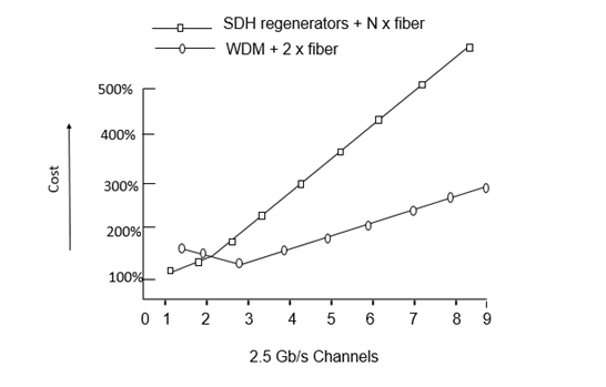
As shown in the following figure, if in addition to the above consideration, the fiber cost is also considered, the cost advantage of WDM case becomes even more evident and is amplified as the number of channels increase. WDM solution is more cost-effective for the deployment of three channels and more in the network.
WDM in the Short Haul
Regenerators are not necessary and optical impairments have less impact because of the limited distances in the short haul networks, hence the benefits of WDM are less clear than those of SDM or enhanced TDM solutions. However, fiber exhaustion and low-cost optical components are now driving WDM in the metropolitan area.
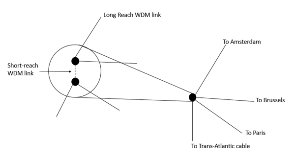
The short-haul application is related to the inter-connection of multiple Points of Presence (POPs) within the same city. Let us consider an example. The following figure shows that the transport network has at least two POPs per city, where the customers can interconnect. With dual node interconnection techniques, such as drop and continue, customer networks can be interconnected with the transport network via two different POPs.
This results in a very secure architecture that can even survive POP failures without any traffic impact. Thus, the traffic flow between two POPs in a city consists of not only traffic that passes through the city, but also of traffic that is terminated in the city and protected using Drop and Continue. These increased intra-city capacity requirements have led to the deployment of WDM in the short-haul section of a transport network.
The main reason WDM is preferred over SDM is because fibers in a city have to be leased from a third party or a fiber optic network has to be built. Leasing or building city fiber is not only an expensive process, it is also a less flexible approach to upgrade capacity. In a dynamic environment, where traffic distributions and volumes evolve rapidly, the amount of fiber to be leased or built is hard to predict in advance. Therefore, using WDM technology has clear flexibility advantages because the wavelength channels can be activated in a very short time.
Although specific short-haul WDM systems are available in the world, it is advantageous to use the same type of WDM system for its long-haul network. While short-haul WDM systems are less expensive than their long-haul counterparts and due to their low-cost optical components can be used, they lead to a heterogeneous network, which is not preferred for several reasons. First, using two different systems leads to an increased operational and management cost. For instance, a heterogeneous network requires more spare equipment parts than a homogeneous network. Second, the interworking between two different systems might pose problems. For instance, a bottleneck can occur because short-haul WDM systems typically support fewer wavelengths than long-haul WDM systems.
Optical Transport Network Architectures
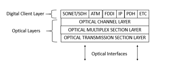
Optical Transport Networking (OTN), as shown in the following figure, represents a natural next step in the evolution of transport networking. From a high-level architectural perspective, one would not expect OTN architectures to differ significantly from those of SDH. Nevertheless, the fact that SDH involves digital network engineering and OTN involves analog network engineering leads to some significant, if subtle distinctions. Exploring these distinctions leads us to an understanding of the aspects of OTN that are likely to differ from their SDH counterparts.
Evolving WDM OTN architectures (including network topologies and survivability schemes) will closely resemble - if not mirror - those for SDH TDM networks. This should be surprising, however, since both SDH and OTN are connection-oriented multiplexed networks. The major differences derive from the form of multiplexing technology: digital TDM for SDH vs analog WDM for an OTN.
The digital vs. analog distinction has a profound effect on the fundamental cost/performance trade-offs in many aspects of OTN network and system design. In particular, the complexities associated with analog network engineering and maintenance implications account for the majority of challenges associated with OTN.
To satisfy the short-term need for capacity gain, WDM point-to-point line systems will continue to be deployed on a large scale. As the number of wavelengths and distance between terminals grow, there is an increasing need to add and/or drop wavelengths at intermediate sites. Hence, flexible reconfigurable Optical ADMs (OADMs) will become integral elements of WDM networks.
As more wavelengths are deployed in carrier networks, there will be an increased need to manage the capacity and hand-off signals between networks at the optical channel level. In much the same way, DXCs emerged to manage the capacity at the electrical layer, Optical Cross-Connects (OXCs) will emerge to manage the capacity at the optical layer.
Initially, the need for optical layer bandwidth management will be the most acute in the core transport network environment. Here, logical mesh-based connectivity will be supported via physical topologies including OADM-based shared protection rings and OXC-based mesh restoration architectures. The choice will depend on the service provider's desired degree of bandwidth "over build" and survivability time scale requirements.
As similar bandwidth management requirements emerge for the metropolitan inter-office and access environments, OADM ring-based solutions will also be optimized for these applications: optical shared protection rings for mesh demands, and optical dedicated protection rings for hubbed demands. Hence, just as the OA was the technology enabler for the emergence of WDM point-to-point line systems, OADMs and OXCs will be the enablers for the emergence of the OTN.
As optical network elements assume the transport layer functionality traditionally provided by SDH equipment, the optical transport layer will come to serve as the unifying transport layer capable of supporting both legacy and converged packet core network signal formats. Of course, service provider movement to OTN will be predicted on the transfer of "SDH-like" transport layer functionality to the optical layer, concurrent with the development of a maintenance philosophy and associated network maintenance features for emerging optical transport layer.
Survivability is central to the role of optical networking as the unifying transport infrastructure. As with many other architectural aspects, optical network survivability will bear a high level resemblance to SDH survivability, since the network topologies and types of network elements are so similar. Within the optical layer, survivability mechanisms will continue to offer the fastest possible recovery from fiber cuts and other physical media faults, as well as provide efficient and flexible management of protection capacity.
OTN is conceptually analogous to SDH, in that sublayers are defined that reflect client-server relationships. Since, OTN and SDH are both connection-oriented multiplexed networks, it should not come as a surprise that the restoration and protection schemes for both are remarkably similar. The subtle but important difference is worth repeating: while TDM networking is based on digital time slot manipulation, OTN/WDM networking is based on analog frequency slot or optical channel (wavelength) manipulation. Thus, while we may expect similar protection and restoration architectures to be possible with both technologies, the types of the network failures for which one may need to account in any particular survivability scheme may be quite different.
Optical Layer Survivability
Telecommunication networks are required to provide reliable uninterrupted service to their customers. The overall availability requirements are of the order of 99.999 per cent or higher, which would imply that the network cannot be down for more than 6 min/year on average. As a result, network survivability is a major factor that affects how these networks are designed and operated. The networks need to be designed to handle link or fiber cuts as well as equipment faults.
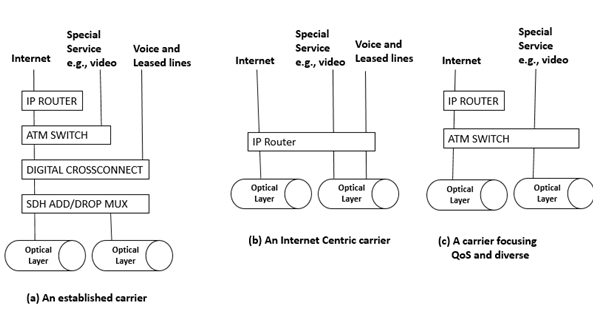
The network may be viewed as consisting of many layers inter-operating with each other, as shown in the above figure. Different carriers choose different ways of realizing their networks using different combinations of layering strategies. Incumbent carriers make use of their large installed base of SDH gear and the extensive grooming and monitoring capabilities of digital cross-connects.
In contrast, a carrier offering Internet Protocol (IP) based services seek to have a simplified network infrastructure using IP as the basic transport layer without using SDH. Carriers that distinguish themselves based on quality (and diversity) of services (QOS) may use ATM as their transport technology. Underneath these layers is the emerging optical WDM layer, or the optical layer.
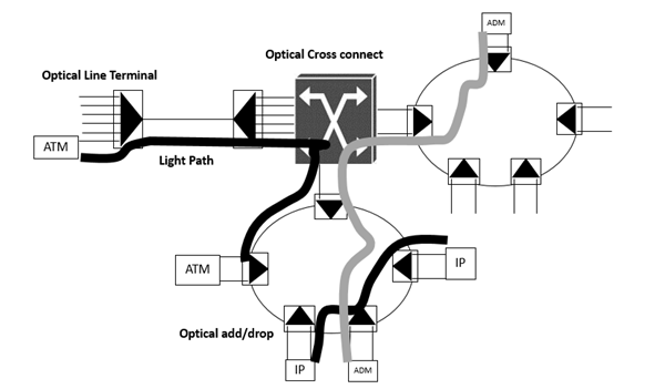
The optical layer provides light-paths to higher layers, which may be considered as client layers that make use of the service provided by the optical layer. Light paths are circuit-switched pipes carrying traffic at fairly high bit rates (e.g., 2.5 Gb/s or 10 Gb/s). These light paths are typically set up to interconnect client-layer equipment, such as SDH ADMs, IP routers, or ATM switches. Once they are set up, they remain fairly static over time.
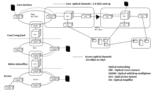
The optical layer consists of Optical Line Terminals (OLTs), Optical ADMs (OADMs), and Optical Cross-Connects (OXCs) as shown in the following figure. OLTs multiplex multiple channels into a single fiber or fiber pair. OADMs drop and add small number of channels from/to an aggregate WDM stream. An OXC, switches and manages large number of channels in a high-traffic node location.
We look at the optical layer protection from a services perspective, in terms of the types of services needed to be provided by the optical layer to the higher layer. We then compare the different optical layer protection schemes that have been proposed in terms of their cost and bandwidth efficiency based on the service mix that must be supported. This is somewhat different, which tend to view optical layer protection as analogous to SDH layer protection.
Why Optical Layer Protection?
The IP, ATM, and SDH layers shown in the above figure, all incorporate protection and restoration techniques. While these layers were all designed to work with other layers, they can also directly operate over fiber, and thus do not depend on other layers to handle the protection and restoration functions. As a result, each of these layers incorporate its own protection and restoration functions. Thus, the question arises, why do we need the optical layer to provide its own set of protection and restoration mechanisms. Following are some of the reasons −
Some of the layers operating above the optical layer may not be fully able to provide all the protection functions needed in the network. For example, the SDH layer was designed to provide comprehensive protection and, therefore, would not rely on the optical layer protection. However, protection techniques in other layers (IP or ATM) by themselves may not be sufficient to provide adequate network availability in the presence of faults.
There are currently many proposals to operate the IP layer directly over the optical layer without using the SDH layer. While IP incorporates fault tolerance at the routing level, this mechanism is cumbersome and not fast enough to provide adequate QOS. In this case, it becomes important for the optical layer to provide fast protection to meet the overall availability requirements from the transport layer.
Most carriers have huge investments in legacy equipment that does not provide protection mechanisms at all, but cannot be ignored. A seamless introduction of the optical layer between this equipment and the raw fiber offers low-cost upgrade of the infrastructure over long fiber links with increased survivability.
Optical layer protection and restoration may be used to provide an additional level of resilience in the network. For example, many transport networks are designed to handle a single failure at a time, but not multiple failures. Optical restoration can be used to provide resilience against multiple failures.
Optical layer protection can be more efficient at handling certain types of failures, such as fiber cuts. A single fiber carries multiple wavelengths of traffic (e.g., 16-32 SDH streams). A fiber cut, therefore, results in all 16-32 of these SDH streams independently being restored by the SDH layer. The network management system is flooded with large number of alarms generated by each of these independent entities. If the fiber cut is restored sufficiently quickly by the optical layer, this operational inefficiency can be avoided.
Significant cost savings can be obtained by making use of optical layer protection and restoration.
Limitations - Optical Layer Protection
Following are some of the limitations of the optical layer protection.
It cannot handle all types of faults in the network. For example, it cannot handle the failure of a laser in an IP router or a SDH ADM attached to the optical network. This type of failure must be handled by the IP or SDH layer, respectively.
It may not be able to detect all types of faults in the network. The light paths provided by the optical layer may be transparent such that they carry data at a variety of bit rates. The optical layer in this case may in fact be unaware of what exactly is carried on these light paths. As a result, it cannot monitor the traffic to sense degradations, such as increased bit error rates, that would normally invoke a protection switch.
The optical layer protects traffic in units of light paths. It cannot provide different levels of protection to different parts of the traffic being carried on the light path (part of the traffic may be high-priority, the other lower priority). This function must be performed by a higher layer that handles traffic at this finer granularity.
There may be link budget constraints that limit the protection capability of the optical layer. For example, the length of the protection route or the number of nodes the protection traffic passes through may be constrained.
If the overall network is not carefully engineered, there may be race conditions when the optical layer and the client layer both try to protect traffic against a failure simultaneously.
The technology and protection techniques are yet to be field tested, and full scale deployment of these new protection mechanisms will, therefore, take a few years to happen.
Definitions of Protected Entities
Before going into the details of the protection techniques and the trade-offs between them, it is beneficial to define the entities that are protected by the optical layer and the client layer. These entities are shown in the following figure.
Client Equipment Port
The ports on the client equipment may fail. In this case, the optical layer cannot protect the client layer by itself.
Intrasite Connections Between the Client and the Optical Equipment
The cables inside a site may be disconnected, mainly due to human errors. This is considered a relatively likely event. Again, full protection against such occurrences can only be supported by combined client-layer and optical-layer protection.
Transponder Cards
Transponders are interface cards between the client equipment and the optical layer. These cards convert the signal from the client equipment into a wavelength that is suitable for use inside the optical network, using optical to electrical to optical conversion. Therefore, the failure rate of this card cannot be considered negligible. Given the large number of these cards in a system (one per wavelength), special protection support for them is in order.
External facilities
This fiber facility between the sites is considered the least reliable components in the system. Fiber cuts are fairly common. This category also includes optical amplifiers that are deployed along the fiber.
Entire nodes
An entire node can fail due to errors by maintenance staff (e.g., tripping power circuit breakers) or entire site failures. Site failures are relatively rare, and usually occur because of natural disasters such as fires, floods, or earthquakes. Node failures have a significant impact on the network and, therefore, still need to be protected against, despite their relatively low probability of occurrence.
Protection Vs Restoration
Protection is defined as the primary mechanism used to deal with a failure. It needs to be very fast (typically traffic should not be interrupted for more than 60 ms in the event of a failure of SDH networks). As a result, the protection routes usually need to be pre-planned so that traffic can be switched over from the normal routes on to the protection routes quickly.
Due to the speed requirements, this function is usually performed in a distributed way by the network elements without relying on a centralized management entity to coordinate the protection actions. With the exception of recent (and not yet proven) fast mesh protection schemes, the protection techniques tend to be fairly simple and are implemented in linear or ring topologies. They all end up using 100 percent access bandwidth in the network.
In contrast, restoration is not a primary mechanism used to deal with failure. After the protection function is complete, restoration is used to provide either efficient routes or additional resilience against further failures before the first failure is fixed. As a result, it can afford to be quite slow (seconds to minutes sometimes).
The restoration routes need not to be preplanned and can be computed on the fly by a centralized management system, without requiring a distributed control function. More sophisticated algorithms can be used to reduce the excess bandwidth required, and more complex mesh topologies can be supported.
Sublayers Within the Optical Layer
The optical layer consists of several sublayers. Protection and restoration can be performed at these different layers. We can have schemes that protect individual light paths or optical channels. These schemes handle fiber cuts as well as failure of terminal equipment, such as lasers or receivers.
We can have schemes that work at the aggregate signal level, which corresponds to the Optical Multiplex Section (OMS) layer. These schemes do not distinguish between different light paths that are multiplexed together, and restore all of them simultaneously by switching them as a group.
The term path-layer protection is used to denote schemes that operate over individual channels or light paths and line layer protection to denote schemes that operate at the optical multiplex section layer. Refer Table 1 for a comparison between the properties of path and line layer schemes, and Table 2 and Table 3 for the different path and line schemes.
Table 1: A Comparison Between Line Protection and Path Protection
| Criterion | Line Protection | Path Protection |
|---|---|---|
| Protects against | Interoffice facilities Site/node failures |
Interoffice facilities Site/node failures Equipment failures |
| Number of fibers | Four, if single-level multiplexing is used | Two |
| Can handle failures/degradation of a single path | No | Yes |
| Supports traffic that must not be protected | No | Yes |
| Equipment cost | Low | High |
| Bandwidth efficiency | Good for protected traffic | Low for unprotected channels |
Table 2: A Comparison Between Line-Layer Schemes
| Scheme | Protects Against | Topology | Constraints/ Deficiencies | Customer Benefits |
|---|---|---|---|---|
| 1+1 line | Line cuts | Point-to-point | Diverse route needed to protect fibers | Simplest to implement and operate |
| 1+1 line | Line cuts | Point-to-point | Diverse route needed to protect fibers | Support for low priority traffic Lower loss (by approx. 3 dB) |
| OULSR | Line cuts Node faults |
Metropolitan ring | Optical layer impairments Further power loss exists due to line-level bridging of signals |
Simple to implement and operate May be done using passive elements (instead of optical switches) |
| OBLSR | Line cuts Node faults |
Metropolitan ring | Optical layer impairments | Protection bandwidth reuse Support for low priority traffic |
| Mesh line Protection | Line cuts Node faults |
Any | Limited by optical layer impairments Based on all-optical cross-connect Hard to manage |
Efficient Low cost |
Table 3: A Comparison Between Path-Layer Schemes
| Scheme | Protects Against | Topology | Constraints/ Deficiencies | Customer Benefits |
|---|---|---|---|---|
| Client layer protection | Client equipment faults Intra-office facilities Transponder faults Interoffice facilities Node faults |
Any | Requires diverse paths in the network Most expensive |
Most extensive protection |
| 1:N equipment protection | Transponder faults | Linear or ring | Very low cost Bandwidth efficient |
|
| 1+1 path or OUPSR | Interoffice facilities Node faults |
Any | Requires diverse paths in the network Bandwidth consuming |
Similar to client protection Simple to develop and operate |
| OBPSR | Interoffice facilities Node faults |
Virtual ring | Protection bandwidth reuse Supports low priority traffic |
|
| Mesh path protection | Interoffice facilities Node faults |
Any | Requires an OXC Very complex to implement and operate |
High efficiency |
The physical network topology can be any mesh, passing light paths between the client equipment nodes. The virtual topology from the client equipment standpoint is restricted as per the client layer (e.g., rings for SDH). 2The physical topology is any mesh, while the virtual topology of the light paths is a ring.
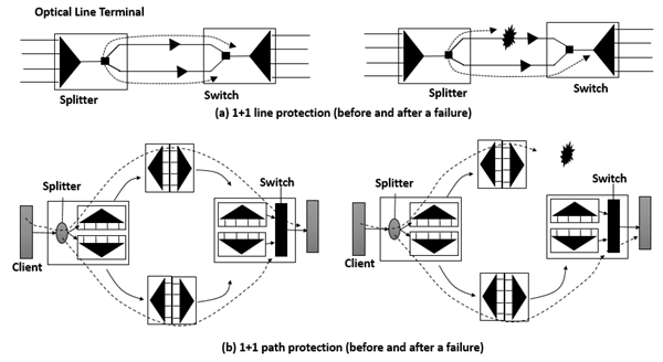
Consider, for example, the two protection schemes shown in the following figures. Both these schemes can be thought of as 1+1 protection schemes, that is, both split the signal at the transmit end and select the better copy at the receiving end. Fig. (a) depicts 1+1 line layer protection, in which both the splitting and selection is done for the entire WDM signal together. Fig. (b) depicts 1+1 path-layer protection, where splitting and selection are done separately for each light path.
Line Layer versus Path Layer Protection
There are important cost and complexity differences between the two approaches. Line protection requires one additional splitter and switch to an unprotected system. However, path protection requires one splitter and switch per channel. More importantly, path protection typically requires twice the transponders and twice the mux/demux resources of line protection. Therefore, path protection is almost twice as expensive as line protection, if all channels are to be protected. The story changes, however, if all the channels need not be protected.
The Basic Protection Schemes
A comparison of protection schemes can be found in Tables -1, 2, and 3. Optical layer protection schemes can be classified in much the same manner as SDH protection schemes and can be implemented at either the client layer, path layer, or line layer.
Client Protection
A simple option is to let the client layer take care of its own protection and not have the optical layer carry out any protection. This may be the case for SDH client layers. While this is simple from the optical layer's perspective, significant cost benefits and bandwidth savings can be obtained by performing optical layer protection. While the client protection method can support point-to-point, ring, or mesh client networks, it is important to note that from the optical network standpoint, all of these translate into optical mesh support, since even a point-to-point client link can span an entire optical mesh network.
In client layer protection, the working and protection client paths are fully diverse routed through the optical layer so that there are no single failure points. Also, the working and protection client paths should not be mapped on to different wavelength over the same WDM link. If WDM link fails, both paths would be lost.
Path Layer Schemes
1+1 Path Protection
This scheme requires two wavelengths across the network, as well as two sets of transponders at each end. When applied to a ring, this protection is also termed as Optical Unidirectional Path Switched Ring (OUPSR) or OCh Dedicated Protection Ring (OCh/DP Ring).
Implementation Notes − Bridging is typically done through an optical coupler, while selection is done via a 1 x 2 optical switch. The receiving end can decide to switch to the backup path without coordination with the source.
Bidirectional Path Switched Ring
This scheme is loosely based on the SDH 4-fiber Bidirectional Line Switched Ring (BLSR) and relies on shared protection bandwidth around the ring. When a working light path fails, the nodes coordinate and try to send the traffic through the designated protection bandwidth in the same direction around the ring (to overcome transponder faults). This is a span switch. If this fails, the nodes loop the traffic around the alternate path around the ring all the way to the other end of the failure. This action is a ring switch.
The scheme allows non-overlapping light paths to share the same protection bandwidth as long as they do not fail together. This scheme is also termed OCh shared protection ring (OCh/SPRing).
Implementation Notes − This scheme can be implemented in an OXC or, through much smaller switches in OADM. Switches are needed for each protection channel. It is similar to SDH BLSR standard.
Mesh Path Protection
This scheme allows global mesh protection with very fast switching (in less than 100 ms) for every failed light path separately to a backup path, shared by multiple light paths potentially taking a different route per light path. In case of a failure, it is intimated to all pertinent nodes that set up backup paths.
Implementation Notes − These schemes are being implemented in OXCs. Due to time constraints, predefined backup paths are stored in the nodes of the network and are activated based on failure types.
Mesh Path Restoration
Unlike mesh path protection, this scheme does not have stringent time constraints. This device computes alternate routes using its topology and disseminates a new setup information to the nodes, which set these routes up. The nodes do not need to maintain any n/w information.
Implementation Notes − The centralized nature of this scheme ensures more optimized protection routes and reduces the implementation and maintenance complexity.
1:N Equipment Protection
One of the most complex (and thus failure-prone) modules in a typical WDM terminal is a transponder. 1:N protection designates a spare transponder to take over in case the normal transponder fails.
Implementation Notes − This scheme more typically is based on a designated protected wavelength. In case of a failure, both ends have to switch using fast signaling protocols, not like APS in SDH.
Line Layer Schemes
1+1 Linear Protection
This scheme is based on bridging the entire WDM signal in bulk onto a pair of diversely routed facilities. The receiving end of these facilities then chooses which of the two signals to receive.
1:1 Linear Protection
This scheme requires a configuration similar to the previous one (i.e., 1+1 linear), however, the signal is switched to either the working or protection path, but not to both. While this increases the coordination burden, it allows running low-priority traffic on the back-up path (until it is needed to protect the working path). It also entails lower optical power loss due to the fact that the entire signal energy is directed to one path instead of two.
Implementation Notes − Switching is typically done using an optical 1×2 switch. Coordination is achieved through a fast-signaling protocol.
Optical Unidirectional Line Switching Ring (OULSR)
The scheme is similar to the OUPSR scheme except that the bridging and selection of signal is done for the aggregate WDM signal. This allows for a more optimized design, lower cost, and very different implementations.
Implementation Notes − An implementation of this scheme is based on passive couplers that run the optical ring into a broadcast medium. Instead of using OADMs, this scheme is based on simple OLTs, each coupled into both clockwise and counter-clockwise rings, so each of the wavelengths is transmitted and received on both fibers. Under normal condition, the link is artificially disconnected, resulting in a linear bus, when the fiber cut link is reconnected.
Bidirectional Line Switched Ring
This scheme is similar to the OBPSR scheme in both the protocol aspects and the protection actions used (span and ring switching). Like all line-layer schemes, the aggregate WDM signal is switched in bulk to a dedicated protect fiber (requiring four fibers), or to a different WDM band within a single fiber (allowing only two fibers, but requiring a two stage optical mux scheme). This scheme is also termed as OMS shared protection ring (OMS/SPRing).
Implementation Notes − As the backup route loops around the entire ring optically, optical line amplifiers may be needed along the backup path to compensate for the losses. The circumference of the ring is also limited by other optical impairments. Therefore, this option fits best in metropolitan applications.
Mesh Line Protection/Restoration
This scheme is based on all-optical cross-connects that divert the WDM signal from a failed facility on to an alternate route and back to the other end of failed facility.
Implementation Notes − Like OBLSR, this scheme is restricted by optical impairments that may develop along alternate routes and requires careful optical design.
Consideration for the Choice of Protection Scheme
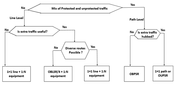
The criteria that could be used by a carrier to select the protection schemes to be used in the network. A simplified decision chart for this is depicted in the following figure assuming both equipment and line protection are needed.
The Cost of Protection
Another criterion from the carrier's standpoint is the cost of the system in at least two aspects −
- Equipment cost
- Bandwidth efficiency
Both of these depend on the service mix of the traffic, that is, the fraction of the traffic to be protected by the optical layer.
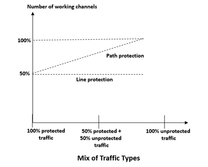
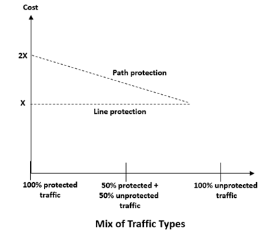
The following figure shows the equipment cost of path layer schemes and equivalent line-layer schemes as a function of the traffic mix. If all the traffic is to be protected, path layer schemes require about twice the equipment of the line-layer schemes as there is less sharing of common equipments.
However, the cost of path layer protection is proportional to the number of channels that are to be protected, as each channel requires an associated mux/demux and terminating equipment. Thus, the cost of path-layer protection drops if fewer channels have to be protected. In case where no channels need to be protected, path-layer schemes will cost about the same as line-layer schemes, assuming that no additional common equipment is deployed.
The story is different from the bandwidth efficiency standpoint, as shown in the following figure. In a line-protected system, the protection bandwidth is consumed for light paths that require protection as well as for those that do not require protection. In path-protection systems, light paths that do not require protection can use bandwidth, allowing other unprotected light paths to use bandwidth that would have been otherwise wasted on unwanted protection.
It follows that if a large portion of the light paths could be left unprotected, path-layer protection recuperates the cost by supporting more working traffic over the same network than line-layer protection.