- Optical Networks - Home
- Optical Networks - Introduction
- Convergence Networks
- Optical Data Networking
- Optical Devices
- Single and Multi-hop Networks
- Optical Networks - WDM Technology
- Optical Networks - ROADM
Optical Networks - ROADM
Legacy optical networks deploy SDH/SONET technologies for transporting data across the optical network. These networks are relatively easy to plan and to engineer. New network elements can be easily added to the network. Static WDM networks may require less investment in equipment, especially in metro networks. However, the planning and maintenance of those networks can be a nightmare as engineering rules and scalability are often quite complex.
Bandwidth and wavelengths must be pre-allocated. As wavelengths are bundled in groups and not all groups are terminated at every node, access to specific wavelengths might be impossible at certain sites. Network extensions might require new Optical-Electrical-Optical regeneration and amplifiers or at least power adjustments in the existing sites. Operating static WDM network is manpower intensive.
Network and bandwidth planning should be as easy as in SDH/SONET networks in the past. Within the given ring bandwidth, for example STM-16 or OC-48 each node could provide as much bandwidth as needed.
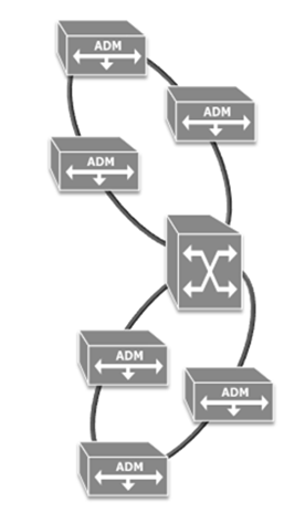
Access to the entire bandwidth was possible at every ADM. Network extension, for example, introduction of a new node in an existing ring, was relatively easy and did not require any on-site visits of the existing nodes. The network diagram on the left illustrates this: Digital cross-connect systems link up with multiple optical SDH/SONET rings.
Reconfigurable optical networks act differently: Bandwidth can be planned on-demand and the reach is optimized as the optical power is now managed per WDM channel. The scalability goes up significantly.
The key element for enabling such a reconfigurable optical network is Reconfigurable Optical Add-drop Multiplexer (ROADM). It enables optical wavelengths to be redirected to client interfaces on just a click in the software. Other traffic remains unaffected by this. All this is achieved without needing any truck rolls to the respective sites to install filters or other equipment.
Reconfigurable WDM Network with ROADMs
Static WDM engineering rules and scalability can be quite complex (OADM in every node).
- Bandwidth and wavelength pre-allocation
- Margin allocation for fixed filter structure
- Insufficient power management
- Network extension requires Optical-Electrical-Optical (OEO) regeneration
SDH/SONET networks are easy to plan.
- Access to entire bandwidth at every ADM
- Easy engineering rules (single hop only)
- Easy addition of new network elements
A reconfigurable optical layer enables the following.
- On-demand bandwidth planning
- Extended transparent reach due to power management per WDM channel
- Hitless scalability
Static photonic layers consist of separate optical rings. Consider a number of DWDM systems located on each of these rings. Frequently information or data simply remains on the same ring, hence there is no issue. However, what happens in cases where data needs to be handed over to a different optical ring?
In static systems, a large number of transponders is required wherever a transition between rings is needed. Actually, each wavelength which passes from one ring to another needs two transponders: one on each side of the network. This approach incurs high costs and a lot of initial planning, considering the allocation of bandwidth and channels.
Let us now imagine a dynamic reconfigurable photonic layer. Here, there is only one single DWDM system forming the interface between two optical rings. Consequently, transponder-based regeneration disappears and the number of DWDM system drops. The whole network design is simplified and wavelengths can now travel from one ring to another without any further obstruction.
Any wavelength can propagate to any ring and to any port. The key to such a fully flexible and scalable network design, with an optical pass-through from the core right to the access area, is the ROADM and the GMPLS control plane.
Simplifications Through ROADMs
ROADMs provide simplifications in the network and in the service providers or carriers processes. This interaction summarizes some of these simplifications. After all, we need to bear in mind that all these advantages result in reduced time effort and cost. But what is more important is that they also lead to increased customer satisfaction and, in turn, customer loyalty.
Network planning is vastly simplified using ROADMs. Just consider the significantly reduced number of transponders, which need to be stocked in the warehouse.
Installation and commissioning for example, when setting up a new wavelength to the network require significantly less effort and are much less complex. Service technicians only need to visit the respective end sites to install the transponders and ROADM. Fixed Optical Add/Drop Multiplexers (FOADMs) used to require a visit to each intermediate site so that installation work and patches could be carried out.
Operations and maintenance are greatly simplified when a dynamic optical network is deployed. Optical diagnostics can be carried out in a few minutes rather than hours, as was previously the case. Impairments can be detected and dynamically cleared instead of triggering truck rolls to external sites.
With the deployment of tunable lasers and colorless ROADMs, the maintenance of the fiber plant is easier. Using these features, service provisioning is now easier than ever before. As with the installation and commissioning work, it is also significantly easier to perform network maintenance and any potential upgrades.
ROADM Architecture
Many advantages ROADMs bring to network design and operation were covered in the previous sections. Here are a few more −
- Per-channel power monitoring and leveling to equalize the entire DWDM signal
- Full traffic control from the remote network operation center
One question, however, has so far been left unanswered: How does a ROADM work? Lets take a look at some fundamentals.
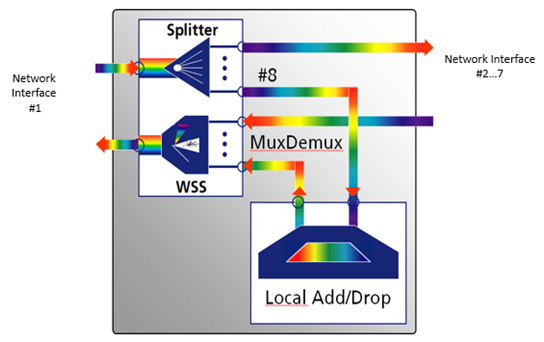
A ROADM generally consists of two major functional elements: A wavelength splitter and a wavelength selective switch (WSS). Take a look at the block diagram above: An optical fiber pair at network interface No. 1 is connected with the ROADM module.
The fiber carrying the incoming data (from the network) is fed to the wavelength splitter. Now, all the wavelengths are available at all output ports of the splitter, in this case 8. Local add/drop traffic (wavelengths) can be multiplexed/de-multiplexed with an Arrayed Waveguide Filter (AWG). Using an AWG implies a fixed wavelength allocation and direction.
The Wavelength Selective Switch (WSS) selectively joins the various wavelengths and feeds them to the output of network interface #1. The remaining splitter ports are connected with other network directions, for example, three other directions at a 4-degree junction node.
Note − One of the illustrated modules (completely grey box) is needed per network direction at this node. Or to be more precise: In a junction node serving four directions (4 degrees) four of these modules are needed.
The ROADM Heart the WSS Module
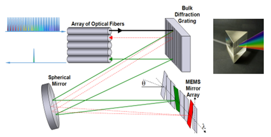
Lets start with the WDM signal coming in from the left. It passes through the optical fiber at the top and is directed towards a bulk diffraction grating. This bulk diffraction grating acts as a kind of prism. It separates the various wavelengths into different directions, though the variation in angle is pretty small. The separated wavelengths hit a spherical mirror, which reflects the rays onto a set of Micro-Electro Mechanical systems (MEMS) for short. Each micro switch is hit by a different wavelength, which is then sent back to the spherical mirror.
From there the rays are returned to the bulk diffraction grating and sent off to the optical fiber. But this is now a different fiber to the one we started with. The single wavelength output signal indicates that this has occurred. This signal can then be combined with other single wavelength signals to fill up another transmission fiber.
There are various versions available the keywords here are colorless, directionless, etc.
ROADM Degrees, Colorless, Directionless, and More
| Term | Explanation |
|---|---|
| Degree | The term Degree describes the number of supported DWDM line interfaces. A 2-degree ROADM node supports two DWDM line interfaces. It also allows two add/drop branches of all line interfaces. |
| Multi Degree | Multi degree ROADMs support more than two DWDM line interfaces. The number of possible add/drop branches is determined by the WSS port count. |
| Colorless | A colorless ROADM enables the flexible allocation of any wavelength or color to any port. Filter modules must be connected for implementing this function. |
| Directionless | A directionless ROADM does not require a physical reconnection of the transmission fibers. Restrictions on directions are eliminated. Directionless ROADMs are deployed for restoration purposes or the temporary re-routing of services (e.g. because of network maintenance or bandwidth on demand requirements). |
| Contentionless | Contentionless ROADMs eliminate the potential problem of two identical wavelengths colliding in the ROADM. |
| Gridless | Gridless ROADMs support various ITU-T channel grids with the same DWDM signal. The grid granularity can be adapted to future transmission speed requirements. |
To understand this leveled ROADM approach, following are some key terms often used in connection with ROADMs.
Colorless
Simple ROADMs comprise one WSS for each direction, also referred to as one degree. The wavelengths are still assigned and fixed add/drop transceivers used. Colorless ROADMs do away with this limitation: With such ROADMs any wavelength or color can be assigned to any port. No truck rolls are required as the complete setup is software-controlled. Filter modules must be implemented for realizing the colorless feature.
Directionless
This often appears in conjunction with the term colorless. A directionless design removes a further ROADM limitation. The need to physically reconnect the transmission fibers is eliminated using directionless ROADMs as there are no restrictions with regard to direction, for example, southbound or northbound.
Contentionless
Though colorless and directionless, ROADMs already offer great flexibility, two wavelengths using the same frequency could still collide in a ROADM. Contentionless ROADMs provide a dedicated internal structure to avoid such blocking.
Gridless
Gridless ROADMs support a very dense wavelength channel grid and can be adapted to future transmission speed requirements. The feature is required for signal rates of more than 100Gbit/s and different modulations formats within one network.
When Directionless
Directionless ROADMs are the most widely spread ROADM design as they allow the add/drop of a wavelength from the supported ITU grid on any line interface. In case of a directionless-only variant, the add/drop ports are specific to a defined wavelength. Using the colorless option, the ports can also be non-wavelength-specific.
The directionless technology is mostly deployed for re-routing wavelength to other ports as required for restoration purposes. Other applications are also possible, for example, in bandwidth-on-demand situations. ROADMs not supporting the directionless feature are subject to some limitations with regard to flexibility.
When Colorless
Colorless ROADMs allow the change of wavelengths of a specific optical channel without any physical re-cabling. A colorless ROADM can be reconfigured to add/drop any wavelength from the supported ITU grid on any add/drop port. The added/dropped wavelength can change (tunable DWDM interface). This enables −
Enhanced flexibility for wavelength provisioning and wavelength restoration
Restoration switching, directional switching, and color switching
The key advantage of colorless add/drop ports in combination with tunable DWDM line interfaces is the enhanced flexibility for wavelength provisioning and wavelength restoration purposes. Automatic tuning to next free wavelength on a requested optical path.
One of the last bits in fully automating the optical network is the deployment of colorless ROADMs. Using such ROADMs allows the add/drop of any wavelength of the supported ITU grid on any add/drop port. The wavelength on the port can change as tunable transceivers are used as optical frontends.
Wavelength provisioning and restoration is made even easier than before. Where a wavelength is busy, the system can automatically tune the transceiver to the next available free wavelength. ROADMs provide the option of using fixed and colorless add/drop features within the same ROADM node.
When Contentionless
Contentionless ROADMs can add/drop any wavelength at any add/drop port without any contention grid on any add/drop port. A dedicated wavelength color can be added/dropped multiple times (from different DWDM line interfaces) on the same add/drop branch. If only 8 add/drop ports are equipped, it must be possible to drop the same wavelength from 8 different line directions on the 8 add/drop ports. As long as free add/drop ports are available, the ROADM node must be able to add/drop any wavelength from/to any line interface.
The combination of Colorless, Directionless, and Contentionless functionality (CDC) provides the ultimate level of flexibility.
When Gridless
Gridless ROADM nodes support different ITU-T channel grids within the same DWDM signal. The grid bandwidth can be provisioned per channel.
The gridless feature is required for networks operating data rates beyond 100Gbit/s or for network operating with different modulation schemes. It is intended for next generation networks with coherent line interfaces. Different data rates demand different wavelength requirements depending on the modulation scheme and data rate.
Transmission speeds are going up and modulation schemes are becoming more and more complex. Several modulation technologies might now be mixed on a single optical fiber. All this reflects back to the ROADM technology and generates the requirements for gridless ROADMs. Such ROADMs operate on a dense frequency grid and allows a per-channel provisioning of the bandwidth. Data channels now demand different wavelengths requirements depending on their modulation scheme and their data rate.
Typical applications are networks operating with data rates beyond 100Gbit/s or running different modulation schemes in parallel. The latter situation can, for example, easily exist when deploying coherent transmission technologies.
