- Optical Networks - Home
- Optical Networks - Introduction
- Convergence Networks
- Optical Data Networking
- Optical Devices
- Single and Multi-hop Networks
- Optical Networks - WDM Technology
- Optical Networks - ROADM
Optical Data Networking
IP over WDM, as defined today, imposes a restrictive view of the capabilities that data networks and optical networks can provide. The constraints, introduced by a single protocol stack and not by fully using the networking capabilities at the optical layer are very restrictive for some network applications.
The networking trends mentioned above require an optical networking platform that can support a variety of protocol stacks, network architectures, and protection and restoration options in a client-signal independent way. The POS over point-to-point WDM choice is best for some of the network applications in high-speed data networks, but certainly not for all. Also, the optical platform selected to implement and deploy these future data networks must ensure that new, unexpected protocol stack mappings can easily be accommodated, and they can receive the same networking features from the optical layer network without the need for an intermediate protocol conversion.
Optical data networking is an alternative approach that does not try to reduce the heterogeneity of protocol stacks and network architectures, but rather exploits the heterogeneity to provide tailored network solutions to each particular application and network provider segment. Optical data networking combines networking features at both the service and transport layers.
Main Component of Optical Data Networking
The diversity of protocol stacks, reflected in the multiplicity of client signal types to be supported in the OTN, is accommodated by the use of digital wrappers. The use of true optical networking features offer additional flexibility and robustness via OCh routing, fault and performance monitoring, protection, and restoration, all performed on a selective per OCh basis. All these elements combined together render a powerful and flexible networking solution that is future-proof and open to any particular vision of data service providers.
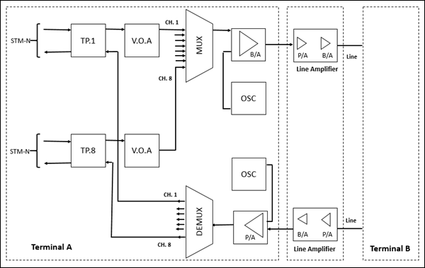
This technology is cost-effective and more flexible for the upgradation of channel capacity, adding/dropping of channels, re-routing and traffic distribution, supporting all types of network topology and protection systems and synchronization. Following are the main components −
- TP (Transponder)
- VOA (Variable Optical Attenuator)
- MUX (Multiplexer)
- DEMUX (De-multiplexer)
- BA (Booster Amplifier)
- Line (OFC media)
- LA (Line Amplifier)
- PA (Pre Amplifier)
- OSC (Optical Supervisory Channel)
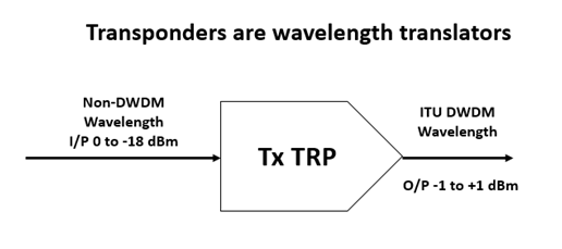
Transponder
This unit is an interface between STM-n wide pulse optical signal and MUX/DEMUX equipments. This optical signal may be co-located or coming from different physical mediums, different protocols, and traffic types. It converts the wide pulse signal into a narrow wavelength (spot or colored frequency) of the order of nano-meter (nm) with spacing of 1.6 nm; sending to MUX.
In the reverse direction, colored output from the DEMUX is converted to a wide pulse optical signal. The output power level is +1 to 3 dBm in both directions. The conversion is Optical to Electrical and Electrical to Optical (O to E & E to O) in 2R or 3R method.
In 2R, regeneration and re-shaping are done, while in 3R, regeneration, re-shaping, and re-timing are performed. TP may be the wavelength color and bit rate dependent or tunable for both (costly and not used). However, in 2R, any bit rate, PDH, STM-4 or STM-16 may be the channel rate. The unit has a limitation with the receiver sensitivity and overload point.
Though the intermediate electrical stage is inaccessible, overhead bytes of STN-n are utilized for supervisory purpose. This unit also supports optical safety operation (ALS) over ITU-T Recommendation G.957.
Variable Optical Attenuator (VOA)
This is a passive network like pre-emphasis required to adjust for uniform distribution of signal level over EDFA band so that individual channel optical output power of Mux unit remains the same irrespective of the number of channels being loaded in the system.
The optical attenuator is similar to a simple potentiometer or circuit used to reduce a signal level. The attenuator is used whenever performance test must be run, for example, to see how the bit error is affected by varying the signal level in the link. One way is to have a precise mechanical setup in which the optical signal passes through a glass plate with differing amount of darkness and then back to the optical fiber, as shown in the figure.
The glass plate has grey density ranging from 0% at one end to 100% at the other end. As the plate is moved across the gap, more or less light energy is allowed to pass. This type of attenuator is very precise, and can handle any light wavelength (since the plate attenuates any light energy by the same amount, regardless of the wavelength), but it is mechanically expensive.
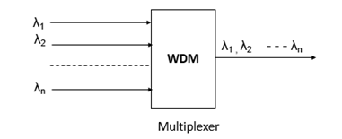
Multiplexer (MUX) and Demultiplexer (De-MUX)
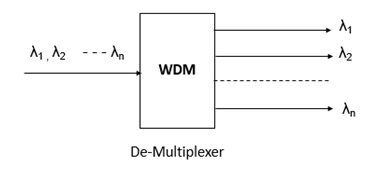
As DWDM systems send signals from several stations over a single fiber, they must include some means to combine the incoming signals. This is done with the help of a Multiplexer, which takes optical wavelengths from multiple fibers and converges them into a beam. At the receiving end, the system must be able to separate out the transmitted wavelengths of the light beam so that they can be discreetly detected.
Demultiplexers perform this function by separating the received beam into its wavelength components and coupling them into individual fibers.
Multiplexers and Demultiplexers can be either passive or active in design. Passive design uses prism, diffraction gratings, or filters while active design combines passive devices with tunable filters.
The primary challenges in these devices are to minimize crosstalk and maximize channel separation (the wavelength difference between two adjacent channels). Crosstalk is a measure of how well the channels are separated, while channel separation refers to the ability to distinguish each wavelength.
Types of Multiplexer/ Demultiplexer
Prism Type
A simple form of multiplexing or demultiplexing of wavelengths can be done using a prism.
A parallel beam of polychromatic light impinges on a prism surface and each component wavelength is refracted differently. This is the rainbow effect. In the output light, each wavelength is separated from the next by an angle. A lens then focuses each wavelength to the point where it needs to enter a fiber. The components can be used in reverse to multiplex different wavelengths on to one fiber.
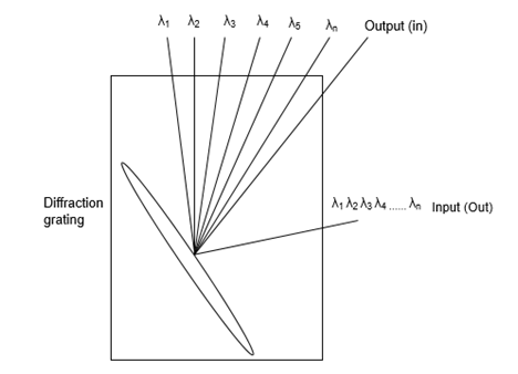
Diffraction Grating Type
Another technology is based on the principle of diffraction and of optical interference. When a polychromatic light source impinges on diffraction grating, each wavelength is diffracted at a different angle and therefore to a different point in space. Using a lens, these wavelengths can be focused on to individual fibers, as shown in the following figure. Bragg grating, is a simple passive component, which can be used as wavelength selective mirrors and are widely used to add and drop channels in DWDM systems.
Braggs grating are made by using an ultra-violet laser beam to illuminate the core of a mono mode fiber through a phase mask. The fiber is doped with phosphorus, germanium, or boron to make it photo sensitive. After the light has passed through the mask, a fringe pattern is produced, which is printed into the fiber. This creates a permanent periodic modulation of the refractive index of the fiber core glass. The finished grating reflects light at the Bragg wavelength (equal to twice the optical spacing between the high and the low index regions) and transmits all other wavelengths.
Tunable Bragg Grating
A Bragg fiber grating can be glued to a piezoelectric element. By applying a voltage to the element, the element stretches so that grating is stretched and the Bragg wavelength shifts to a longer wavelength. Present devices can provide a tuning range of 2 nm for an input of 150v.
Arrayed Waveguide Grating
Arrayed Waveguide Gratings (AWG) are also based on diffraction principles. An AWG device, sometimes called an optical waveguide router or waveguide grating router, consists of an array of curved channel waveguide with a fixed difference in the path length between adjacent channels. The waveguides are connected to cavities at the input and output.
Optical Multiplexer
When the light enters the input cavity, it is diffracted and enters the wave-guide array. Thus the optical length difference of each wave guide introduces phase delays in the output cavity, where an array of fibers is coupled. The process results in different wavelengths having maximum interference at different location, which corresponds to the output ports.
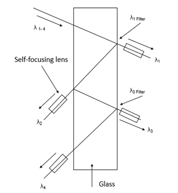
Multilayer Interference Filters
A different technology uses interference filters in devices called thin film filters or multilayer interference filters. By positioning the filters, consisting of thin films in the optical path, wavelength can be demultiplexed. The property of each filter is such that it transmits one wavelength, while reflecting others. By cascading these devices, many wavelengths can be demultiplexed.
Filters offer good stability and isolation between channels at moderate cost, but with a high insertion loss (AWGs exhibit a flat spectral response and low insertion loss). The main drawback of the filter is that they are temperature sensitive and may not be practically used in all environments. However, their big advantage is that they can be designed to perform multiplexing and demultiplexing operations simultaneously.
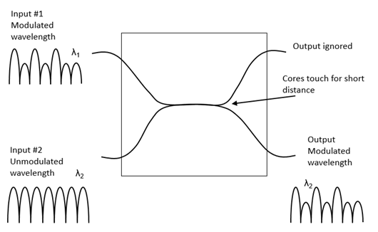
Coupling Type of the OM
The coupling OM is a surface interactive with two or more fibers soldered together. Generally, it is used for the OM, and its working principles are illustrated in the following figure.
The coupling OM can only perform multiplexing function with low manufacture cost. Its shortcoming is high insertion loss. Presently, the OM used in the DWDM equipment of ZTWE employs the coupling OM. The OD adopts the AWG components.
Booster Amplifiers (Optical Amplifiers)
Due to attenuation, there are limits to how long a fiber segment can propagate a signal with integrity, before it has to be regenerated. Before the arrival of Optical Amplifiers (OAs), there had to be a repeater for every signal transmitted. The OA had made it possible to amplify all the wavelengths at once and without Optical-Electrical-Optical (OEO) conversion. Besides being used in optical links (as repeater), optical amplifiers can also be used to boost signal power after multiplexing or before demultiplexing.
Types of Optical Amplifiers
In every optical route, the optical amplifiers were used as repeaters in a simplex mode. One fiber was used in send path and the second fiber was used in return path. The latest optical amplifiers will operate in two directions at the same time. We can even use the same wavelength in two directions, provided two different bit rates are employed. A single fiber can, therefore, be used for duplex operation.
The optical amplifiers must also have sufficient bandwidth to pass a range of signals operating at different wavelengths. For example, an SLA with a spectral bandwidth of say, 40 nm, can handle about ten optical signals.
In 565 mb/s system, for 500 kms optical link, five SLA optical amplifiers are required, spaced at an interval of 83 kms. Each amplifier provides a gain of about 12 dB, but also introduces noise to the system (BER of 10-9.)
SLA amplifiers have the following disadvantages −
- Sensitive to temperature changes
- Sensitive to supply voltage changes
- Sensitive to mechanical vibrations
- Unreliable
- Prone to crosstalk
Erbium Doped Fiber Amplifier (EDFA)
In DWDM systems, EDFAs are used. Erbium is a rare earth element that, when excited, emits light around 1.54 micrometers, which is the low loss wavelength for optical fibers used in DWDM. A weak signal enters the erbium-doped fiber, into which light at 980 nm or 1480 nm is injected using a pump laser.
This injected light stimulates the erbium atoms to release their stored energy as additional 1550 nm light. The signal grows strong. The spontaneous emissions in the EDFAs also add noise figure of an EDFA. EDFAs have a typical bandwidth of 100 nm and are needed at an interval of 80-120 kms along the optical route.
EDFA also suffer from an affect called four-wave-mixing due to non-linear interaction between the adjacent channels. Hence, increasing the amplifier power to increase the distance between the repeaters leads to more crosstalk.
Raman Amplifier
The use of SLA and EDFA amplifiers in WDM is limited as already described and, the modern WDM systems are turning to Raman Amplification, which has a bandwidth of about 300 nm. Here, the pump laser is at the receiving end of the fiber. Crosstalk and noise are greatly reduced. However, Raman amplification requires a high pump laser to be used.
Dispersion in the fiber actually helps to minimize the four wave mixing effect. Unfortunately, early optical links often used zero-dispersion fiber in an effort to minimize dispersion over long distances, when these same fibers are upgraded to carry WDM signals; they are not the ideal medium for wideband optical signals.
Special mono mode fibers are being developed for WDM use. These have alternate segments of positive and negative dispersion fibers, hence, the total dispersion adds up to zero. The individual segments, however, provide dispersion to prevent four-wave mixing.
Line Amplifiers
It is a two-stage EDFA amplifier consisting of Pre-amplifier (PA) and Booster Amplifier (BA). Without the two stages, it is not possible to amplify the signal up to 33 dB on EDFA principle (to avoid the noise generated by spontaneous emission). Line Amplifier (LA) compensates the line loss of 22 dB or 33 dB for long and very long haul systems respectively. It is entirely an optical stage device.
Line (OFC) Media
This is the optical fiber media over which the DWDM signals travel. Attenuation and dispersion are the main limitation factors determining the transmission distance, bit-rate capacity, etc. Normally, 22dB and 33dB are taken as line loss for hop length of long haul and very long haul systems, respectively.
The very long haul line wavelength can be 120 kms without repeater (LA). However, with a number of repeaters cascaded, the length may be up to 600 kms, which can further be, increased up to 1200 kms using the dispersion compensating module. After such a distance, it needs re-generation in electrical stage instead of the repeater in only the optical stage.
Pre-Amplifier (PA)
This amplifier alone is used at the terminal to interface the DEMUX and line for receiving the signal coming from the distant station. Hence, the attenuated line signal is amplified to a level of +3 dBm to 10 dBm before entering into DEMUX unit.
Optical Supervisory Channel
The function of transmission of additional data (2 mbps: EOW, user specific data etc via interface) at a separate wavelength (1480 nm as per ITU-T Recommendation G-692) of lower optical level without any optical safety provision, accompanied with and independent of the main STM-n optical traffic signal, is performed by the OSC. EOW (0.3 to 3.4 KHz) for selective and omnibus channel is 64 kbps in 8-bit PCM code.
The Optical Supervisory Channel (OSC) helps control and monitor the optical line devices as well as the management of fault location, configuration, performance and security accomplished using LCT.
