
Article Categories
- All Categories
-
 Data Structure
-
 Networking
-
 RDBMS
RDBMS
-
 Operating System
-
 Java
Java
-
 MS Excel
-
 iOS
iOS
-
 HTML
HTML
-
 CSS
CSS
-
 Android
-
 Python
-
 C Programming
-
 C++
C++
-
 C#
C#
-
 MongoDB
-
 MySQL
MySQL
-
 Javascript
-
 PHP
PHP
-
 Economics & Finance
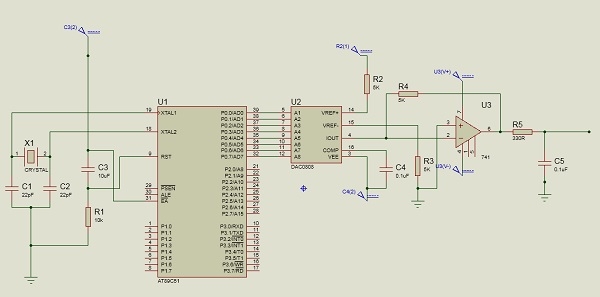
Interfacing DAC with 8051 Microcontroller
In this section we will see how DAC (Digital to Analog Converter) using Intel 8051 Microcontroller. We will also see the sinewave generation using DAC.
The Digital to Analog converter (DAC) is a device, that is widely used for converting digital pulses to analog signals. There are two methods of converting digital signals to analog signals. These two methods are binary weighted method and R/2R ladder method. In this article we will use the MC1408 (DAC0808) Digital to Analog Converter. This chip uses R/2R ladder method. This method can achieve a much higher degree of precision. DACs are judged by its resolution. The resolution is a function of the number of binary inputs. The most common input counts are 8, 10, 12 etc. Number of data inputs decides the resolution of DAC. So if there are n digital input pin, there are 2n analog levels. So 8 input DAC has 256 discrete voltage levels.
The MC1408 DAC (or DAC0808)
In this chip the digital inputs are converted to current. The output current is known as Iout by connecting a resistor to the output to convert into voltage. The total current provided by the Iout pin is basically a function of the binary numbers at the input pins D0 - D7 (D0 is the LSB and D7 is the MSB) of DAC0808 and the reference current Iref. The following formula is showing the function of Iout
$$I_{Out}=I_{ref}\lgroup\frac{D7}{2}+\frac{D6}{4}+\frac{D5}{8}+\frac{D4}{16}+\frac{D3}{32}+\frac{D2}{64}+\frac{D1}{128}+\frac{D0}{256}\rgroup$$
The Iref is the input current. This must be provided into the pin 14. Generally 2.0mA is used as Iref
We connect the Iout pin to the resistor to convert the current to voltage. But in real life it may cause inaccuracy since the input resistance of the load will also affect the output voltage. So practically Iref current input is isolated by connecting it to an Op-Amp with Rf = 5K? as feedback resistor. The feedback resistor value can be changed as per requirement.
Generating Sinewave using DAC and 8051 Microcontroller
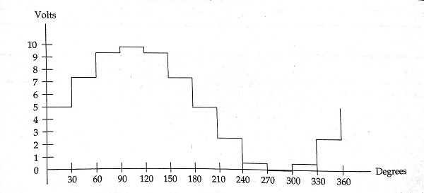
For generating sinewave, at first we need a look-up table to represent the magnitude of the sine value of angles between 0° to 360°. The sine function varies from -1 to +1. In the table only integer values are applicable for DAC input. In this example we will consider 30° increments and calculate the values from degree to DAC input. We are assuming full-scale voltage of 10V for DAC output. We can follow this formula to get the voltage ranges.
V<sub>out</sub> = 5V + (5 ×sin?)
Let us see the lookup table according to the angle and other parameters for DAC.
| Angle(in ? ) | sin? | Vout (Voltage Magnitude) | Values sent to DAC |
|---|---|---|---|
| 0 | 0 | 5 | 128 |
| 30 | 0.5 | 7.5 | 192 |
| 60 | 0.866 | 9.33 | 238 |
| 90 | 1.0 | 10 | 255 |
| 120 | 0.866 | 9.33 | 238 |
| 150 | 0.5 | 7.5 | 192 |
| 180 | 0 | 5 | 128 |
| 210 | -0.5 | 2.5 | 64 |
| 240 | -0.866 | 0.669 | 17 |
| 270 | -1.0 | 0 | 0 |
| 300 | -0.866 | 0.669 | 17 |
| 330 | -0.5 | 2.5 | 64 |
| 360 | 0 | 5 | 128 |
Circuit Diagram ?
Source Code
<span class="com">#include</span><span class="str"><reg51.h></span><span class="pln">
sfr DAC </span><span class="pun">=</span><span class="pln"> </span><span class="lit">0x80</span><span class="pun">;</span><span class="pln"> </span><span class="com">//Port P0 address</span><span class="pln">
</span><span class="kwd">void</span><span class="pln"> main</span><span class="pun">(){</span><span class="pln">
   </span><span class="kwd">int</span><span class="pln"> sin_value</span><span class="pun">[</span><span class="lit">12</span><span class="pun">]</span><span class="pln"> </span><span class="pun">=</span><span class="pln"> </span><span class="pun">{</span><span class="lit">128</span><span class="pun">,</span><span class="lit">192</span><span class="pun">,</span><span class="lit">238</span><span class="pun">,</span><span class="lit">255</span><span class="pun">,</span><span class="lit">238</span><span class="pun">,</span><span class="lit">192</span><span class="pun">,</span><span class="lit">128</span><span class="pun">,</span><span class="lit">64</span><span class="pun">,</span><span class="lit">17</span><span class="pun">,</span><span class="lit">0</span><span class="pun">,</span><span class="lit">17</span><span class="pun">,</span><span class="lit">64</span><span class="pun">};</span><span class="pln">
   </span><span class="kwd">int</span><span class="pln"> i</span><span class="pun">;</span><span class="pln">
   </span><span class="kwd">while</span><span class="pun">(</span><span class="lit">1</span><span class="pun">){</span><span class="pln">
      </span><span class="com">//infinite loop for LED blinking</span><span class="pln">
      </span><span class="kwd">for</span><span class="pun">(</span><span class="pln">i </span><span class="pun">=</span><span class="pln"> </span><span class="lit">0</span><span class="pun">;</span><span class="pln"> i</span><span class="pun"><</span><span class="lit">12</span><span class="pun">;</span><span class="pln"> i</span><span class="pun">++){</span><span class="pln">
         DAC </span><span class="pun">=</span><span class="pln"> sin_value</span><span class="pun">[</span><span class="pln">i</span><span class="pun">];</span><span class="pln">
      </span><span class="pun">}</span><span class="pln">
   </span><span class="pun">}</span><span class="pln">
</span><span class="pun">}</span>
Output
The output will look like this ?

54K+ Views
