- Data Comm & Networks Home
- DCN - Overview
- DCN - What is Computer Network
- DCN - Uses of Computer Network
- DCN - Computer Network Types
- DCN - Network LAN Technologies
- DCN - Computer Network Models
- DCN - Computer Network Security
- DCN - Components
- DCN - Connectors
- DCN - Switches
- DCN - Repeaters
- DCN - Gateways
- DCN - Bridges
- DCN - Socket
- DCN - Network Interface Card
- DCN - NIC: Pros and Cons
- DCN - Network Hardware
- DCN - Network Port
- Computer Network Topologies
- DCN - Computer Network Topologies
- DCN - Point-to-point Topology
- DCN - Bus Topology
- DCN - Star Topology
- DCN - Ring Topology
- DCN - Mesh Topology
- DCN - Tree Topology
- DCN - Hybrid Topology
- Physical Layer
- DCN - Physical Layer Introduction
- DCN - Digital Transmission
- DCN - Analog Transmission
- DCN - Transmission media
- DCN - Wireless Transmission
- DCN - Transmission Impairments
- DCN - Multiplexing
- DCN - Network Switching
- DCN - Circuit Switching
- DCN - Packet Switching
- DCN - Message Switching
- Data Link Layer
- DCN - Data Link Layer Introduction
- DCN - Data Link Control & Protocols
- DCN - RMON
- DCN - Token Ring Network
- DCN - Hamming Code
- DCN - Byte Stuffing
- DCN - Channel Allocation
- DCN - MAC Address
- DCN - Address Resolution Protocol
- DCN - Cyclic Redundancy Checks
- DCN - Error Control
- DCN - Flow Control
- DCN - Framing
- DCN - Error Detection & Correction
- DCN - Error Correcting Codes
- DCN - Parity Bits
- Network Layer
- DCN - Network Layer Introduction
- DCN - Network Addressing
- DCN - Routing
- DCN - Routing Table
- DCN - Internetworking
- DCN - Network Layer Protocols
- DCN - Routing Information Protocol
- DCN - Border Gateway Protocol
- DCN - OSPF Protocol
- DCN - Network Address Translation
- DCN - Network Address Translation Types
- Transport Layer
- DCN - Transport Layer Introduction
- DCN - Transmission Control Protocol
- DCN - User Datagram Protocol
- DCN - Congestion Control
- DCN - Open Loop Congestion Control
- DCN - Closed Loop Congestion Control
- DCN - Congestion Control Algorithms
- DCN - Token Bucket Algorithm
- DCN - TCP Tahoe Algorithm
- DCN - TCP Reno Algorithm
- DCN - TCP New Reno Algorithm
- DCN - TCP BIC Algorithm
- DCN - TCP CUBIC Algorithm
- DCN - TCP Service Model
- DCN - TLS Handshake
- DCN - TCP Vs. UDP
- Application Layer
- DCN - Session Layer
- DCN - Presentation Layer
- DCN - Application Layer Introduction
- DCN - Client-Server Model
- DCN - Application Protocols
- DCN - Network Services
- DCN - Virtual Private Network
- DCN - Load Shedding
- DCN - Optimality Principle
- DCN - Service Primitives
- DCN - Services of Network Security
- DCN - Hypertext Transfer Protocol
- DCN - File Transfer Protocol
- DCN - Secure Socket Layer
- Network Protocols
- DCN - ALOHA Protocol
- DCN - Pure ALOHA Protocol
- DCN - Sliding Window Protocol
- DCN - Stop and Wait Protocol
- DCN - Link State Routing
- DCN - Link State Routing Protocol
- Network Algorithms
- DCN - Shortest Path Algorithm
- DCN - Routing Algorithm
- DCN - Adaptive Routing Algorithms
- DCN - Non-Adaptive Routing Algorithms
- DCN - Leaky Bucket Algorithm
- Wireless Networks
- DCN - Wireless Networks
- DCN - Wireless LANs
- DCN - Wireless LAN & IEEE 802.11
- DCN - IEEE 802.11 Wireless LAN Standards
- DCN - IEEE 802.11 Networks
- Multiplexing
- DCN - Multiplexing & Its Types
- DCN - Time Division Multiplexing
- DCN - Synchronous TDM
- DCN - Asynchronous TDM
- DCN - Synchronous Vs. Asynchronous TDM
- DCN - Frequency Division Multiplexing
- DCN - TDM Vs. FDM
- DCN - Code Division Multiplexing
- DCN - Wavelength Division Multiplexing
- Miscellaneous
- DCN - Shortest Path Routing
- DCN - B-ISDN Reference Model
- DCN - Design Issues For Layers
- DCN - Selective-repeat ARQ
- DCN - Flooding
- DCN - E-Mail Format
- DCN - Cryptography
- DCN - Unicast, Broadcast, & Multicast
- DCN - Network Virtualization
- DCN - Flow Vs. Congestion Control
- DCN - Asynchronous Transfer Mode
- DCN - ATM Networks
- DCN - Synchronous Vs. Asynchronous Transmission
- DCN - Network Attacks
- DCN - WiMax
- DCN - Buffering
- DCN - Authentication
- DCN Useful Resources
- DCN - Quick Guide
- DCN - Useful Resources
- DCN - Discussion
Synchronous Time Division Multiplexing
Synchronous Time Division Multiplexing
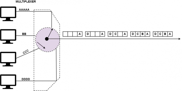
In the Synchronous Time Division Multiplexing (STDM), the multiplexer assigns an equal time slot to every device at all times, whether or not a device has anything to send. Time slot A, for instance, is authorised to device A alone and cannot be used by any other device.
Each time is assigned a time slot and it shows up. Then, a device has the time to transmit a portion of its data. If a device cannot send or does not have data to send, its time slot remains null.
The time slots are consolidated into frames, and every frame includes one or more time slots committed to each sending device. If there are n sending devices, the frame consists of n slots, where each slot will be allocated to each of the sending devices. This happens if all the sending devices transmit at the same rate as shown in the figure.
In the diagram given below, there are four inputs to multiplexer A. Each frame is having four slots corresponding to each of the sending devices.

Interleaving
Synchronous Time Division Multiplexing (TDM) can be distinguished to a high-speed rotating switch. As the switch is free in front of a device, that device can transmit a particular record of data onto the direction. The switch transfers from device to device at a fixed price and in a permanent order. This process is called interleaving.
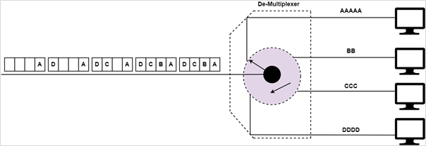
At the receiver, the demultiplexer disintegrates every frame by obtaining each character in turn. As a character is eliminated from a frame, it is moved to the suitable receiving device, as demonstrated in the figure below.
Disadvantage
The disadvantages of Synchronous TDM are as follows
-
In synchronous time-division multiplexing, an equal time slot is given to each sender to load its data on the channel.
-
Different senders load different volumes of data, and frames are usually empty.
