
Article Categories
- All Categories
-
 Data Structure
-
 Networking
-
 RDBMS
RDBMS
-
 Operating System
-
 Java
Java
-
 MS Excel
-
 iOS
iOS
-
 HTML
HTML
-
 CSS
CSS
-
 Android
-
 Python
-
 C Programming
-
 C++
C++
-
 C#
C#
-
 MongoDB
-
 MySQL
MySQL
-
 Javascript
-
 PHP
PHP
-
 Economics & Finance
Analog & Digital Multimeter
Multimeter
As the name implies, a multimeter is device that can be used to measure multiple quantities, i.e., when a single device is used to measure multiple quantities, the device is called multimeter. On the basis of output representation, there are two types of multimeters −
- Analog multimeter
- Digital multimeter
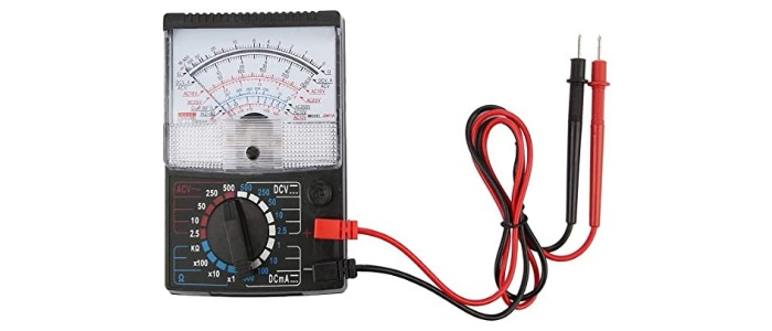
Analog Multimeter
An analog multimeter is a permanent magnet moving coil (PMMC) meter type measuring instrument. It works on the principle of d’Arsonval galvanometer. The analog multimeter has an analog display that uses the deflection of a pointer on the scale to indicate the level of measurement being made. The pointer deflects from its initial position increasingly as the measuring quantity increases.
Working of Analog Multimeter
Since, the analog multimeter is a PMMC types instrument, so when a current is passed through its coil, the coil moves in a magnetic field produced by the permanent magnet. A pointer is attached with the coil. When current flows in the coil, a deflecting torque acts on the coil that will rotate it by an angle, so the pointer moves over a scale. A pair of hairsprings is attached to the spindle to provide the controlling torque.
Analog Multimeter Measuring Quantities
A typical analog multimeter can measure following electrical quantities −
- DC Voltage
- AC Voltage
- DC Current
- Resistance
The analog multimeter acts as an ammeter with a low series resistance to measure direct current. For high currents measurement, a shunt resistor is connected in parallel with the galvanometer. With the shunt resistor, an analog multimeter can measure currents in the ranges of milli-amperes or amperes.
By adding a multiplier resistor an analog multimeter becomes a voltmeter and can be used for the measurement of DC voltage in the ranges of milli-volts or kilo volts.
By adding a battery and a network of resistors, the analog multimeter can work as an ohmmeter. By changing the value of shunt resistance in resistor network, different values of resistances can be measured.
By adding a rectifier unit in the analog multimeter circuit, the AC voltages and currents can also be measured.
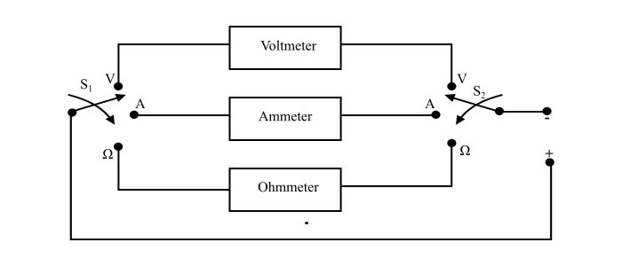
Block Diagram of Analog Multimeter
Here, two switches S1 and S2 are used to select the desired meter. It also has a rotary range-selector switch to choose a particular range of current, voltage and resistance.
Operation of Analog Multimeter
The analog multimeter is very easy to use. With the knowledge of how to make voltage, current and resistance measurements, it is only necessary to know how to use the analog multimeter.
For the measurement of current and voltage, there is no need of batteries in the analog multimeter. But, if resistance is to be measured, batteries need to be installed in the multimeter.
Steps for the use of analog multimeter −
Insert the probes into the correct connections.
Set switch to the correct measurement types and range for the measurement to be made. While selecting the range, ensure that the maximum range is above than that is expected. The range of multimeter is then optimised for the best reading.
Once the measurement is completed, it is wise precaution to place the probes into the voltage measurement sockets and set the range to maximum voltage. In this way if the meter is accidently connected across a high voltage point, there is a little chance of damage to the multimeter.
Advantages of Analog Multimeter
It gives the continuous reading, thus a sudden change in signal can be detected which is not possible with digital multimeter.
Analog multimeter are very cheap.
All measurement can be made using a single meter only.
Disadvantages of Analog Multimeter
They are bulky and larger sized.
Multiple scales, these can cause confusion.
Low input resistance.
Analog multimeters do not have auto-polarity function. Therefore, it is necessary to connect probes correctly.
Less accurate than a digital multimeter.
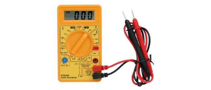
Digital Multimeter
A digital multimeter (DMM) is a measuring instrument used to measure various electrical quantities. The standard measurements that are performed by a DMM are current, voltage and resistance. Apart from these, a digital multimeter can also measure temperature, frequency, capacitance, continuity, transistor gains etc.
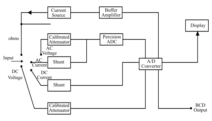
Block Diagram of Digital Multimeter
DMM Controls and Connection Ports
A typical DMM has a rotary switch, digital display and connecting jacks for the probes. Let’s see the various parts of DMM in somewhat details −
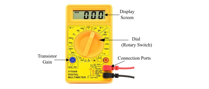
Display − The DMM has an illuminated display screen for better visualisation. Most DMM have four digit display, the first of which can only be either a 0 or 1 and a + / - indication as well. There may also be some more indicators like AC / DC etc.
-
Connection Ports − There are three or four ports available on the front of the DMM. However, only two are needed at a time. Typical ports of the DMM are −
Common − It is used with all measurements. The negative (black) probe is connected to this.
VΩmA Port − This port is used for the most measurements and positive (red)probe is connected to it.
10A Port − It is used to measure the large currents in the circuits.
Dial (Selection Knob) − There is a rotary switch to select the types of measurement to be made and range that is needed.
Additional Connections − There are some additional connections in DMM for other measurements like temperature, transistor gains etc.
Additional Buttons and switches − There are a few additional buttons are present in a DMM. The main one is ON/OFF button.
Measurements using Digital Multimeter
In AC Voltage Mode − The applied input voltage is fed through a calibrated,compensated attenuator, to a full-wave rectifier followed by a ripple reduction filter.The resulting DC is fed to analog to digital converter (ADC) and finally to the display system.
-
For Current Measurement −
In DC Current Mode − The drop across an internal calibrated shunt is measured directly by the ADC.
In AC Current Mode − After AC to DC conversion, the drop across the internal calibrated shunt is measured by the ADC
In Resistance Mode − In the resistance range, the digital multimeter operates by measuring the voltage across the externally connected resistor, resulting from a current flowing through it from a calibrated internal current source.
Operation of Digital Multimeter
With the knowledge of how to make voltage, current and resistance measurements, the operation of DMM is quite easy. It is necessary to install a battery in the DMM to power it.
Steps for the use of digital multimeter −
Turn the meter ON.
Insert the probes into the correct connecting ports.
Set the dial (rotary switch) to the correct measurement type and range for the measurement to be made. While selecting the range, ensure that the maximum range is above than that is expected. Optimise the range for the best reading. If possible enable all the leading digits to not read zero, in this way the greatest number of significant digits can be read.
Once the measurement is completed, it is a wise precaution to place the probes into the voltage measurement ports and turn the range to maximum voltage. So that if the meter probes are accidentally connected across a high voltage point, there is a little chance of damage to the DMM.
Advantages of Digital Multimeter
- Cheap and easily available.
- Auto range according to requirements.
- Smaller size and light in weight.
- Auto off.
- Auto polarity, etc.

25K+ Views
