
Article Categories
- All Categories
-
 Data Structure
-
 Networking
-
 RDBMS
RDBMS
-
 Operating System
-
 Java
Java
-
 MS Excel
-
 iOS
iOS
-
 HTML
HTML
-
 CSS
CSS
-
 Android
-
 Python
-
 C Programming
-
 C++
C++
-
 C#
C#
-
 MongoDB
-
 MySQL
MySQL
-
 Javascript
-
 PHP
PHP
-
 Economics & Finance
Working of 74138 decoder IC
Let’s take an Integrated Circuit decoder. We take the popular 3 to 8 decoder Integrated Circuit 74138. The Integrated Circuit is of 16 pins.
We have three input pins which are actively in high state and are classified as I2, I1 and I0. The outputs are actively in low state and are eight in number and are classified as O7*, O6*, …, O0*. A power supply of +5 V DC is needed by the chip and is Grounded.
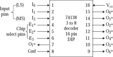
Fig. Diagram in functional mode of 74138
The point to be noted that, only one of the lines of output which completely depends on the input pins I2, I1, and I0. Let’s take as an example that if the pins I2 I1 I0 = 1 1 1, then the line of output O7* is equal to 0, rather line O7* gets activated. If by chance I2 I1 I0 is equal to 0 1 0, then the lines of output O2* turns to 0. Moreover, the lines of output get activated by the input, if and only if 74138 chip becomes selected. The chip 74138 gets selected when E1* turns to 0, and E2* is equal to 0, and E3 is 1. Here EPROM-7 gets selected when 74138 is selected and the address A12 A11 A10 turns to 1 1 1. Here EPROM-7 gets selected when 74138 is selected and the address A12 A11 A10 turns to 1 1 1. The lines of address ranging from A9 to A0 selects a particular location in the EPROM-7 after 74138 and here after EPROM-7 gets selected. So the address of starting becomes
A15 to A13: Selects 74138 0 0 1
A12 to A10: Selects an EPROM 0 0 0
A9 to A0: Selects a location in EPROM 0 0 0 0 0 0 0 0 0 0
So the ultimate address bit pattern has become 0 0 1 0 0 0 0 0 0 0 0 0 0 0 0 0 => 2000H
Use of 74138 to generate chip select logic:
We use the logic of selection to generate signals for chip selection tending to eight chips in a microcomputer system. Let us suppose that there are eight 1K × 8 sized chips of EPROM, where we want the starting of address to be 2000H, 2400H, 2800H, …, 3C00H.
In the figure below 74138 gets selected when the addresses A15 A14 A13 turns to 0 0 1. EPROM-0 gets selected when selection of 74138 is done and A12 A11 A10 turns to 0 0 0. The lines of address ranging from A9-0 gets selects by the memory location in the EPROM to be 0 thereafter 74138 and EPROM-0 is finally selected. Hence the address of starting for EPROM-0 is depicted in the following figure -
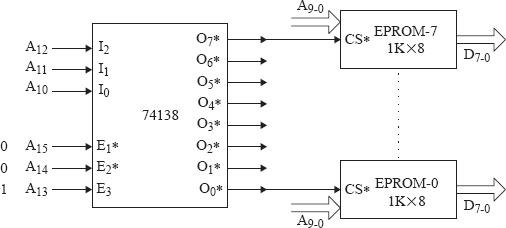
Fig. 74138 is used to generate chip signals.
Here
A15 to A11 selects RAM A10 to A0 selects a location in RAM
1 1 0 0 0 1 0 0 0 0 0 0 0 0 0 0 => C400H
We select EPROM-7 gets selected when the selection of 74138 is done A12 A11 A10 turns to 1 1 1. The lines of address ranging from A9 to A0 selects a particular location in the EPROM-7 after 74138 and here after EPROM-7 gets selected.
Disadvantage:
If 74138 is not used, we have separate circuits for chip selection which results to complex circuits.
Circuit would be very expensive

9K+ Views
