
Article Categories
- All Categories
-
 Data Structure
-
 Networking
-
 RDBMS
RDBMS
-
 Operating System
-
 Java
Java
-
 MS Excel
-
 iOS
iOS
-
 HTML
HTML
-
 CSS
CSS
-
 Android
-
 Python
-
 C Programming
-
 C++
C++
-
 C#
C#
-
 MongoDB
-
 MySQL
MySQL
-
 Javascript
-
 PHP
PHP
-
 Economics & Finance
What is the difference between Latch and Flip-Flops in computer architecture?
Latch
A latch is a device with particularly two stable states and these states are high-output and low-output. A latch has a feedback direction, to maintain the data. Latches can be memory devices and can save one bit of information. It is used to “latch onto” data and save it in the required area. One of the most generally used latches is the SR latch.
An SR latch is an asynchronous device. An SR latch does not rely upon control signals but relies only on the state of the S and R inputs. An SR latch can be generated by interlinking two NOR gates with a cross-feedback loop. SR latches can be constructed by interlinking NAND gates but the inputs are exchanged and contradict.
Flip-Flop
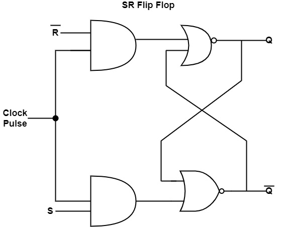
Flip flops are an application of logic gates. A flip-flop circuit can stay in a binary state continually (considering power is transferred to the circuit) before conducted by an input signal to switch states. S-R flip-flop represents SET-RESET flip-flops. The SET-RESET flip-flop includes two NOR gates and also two NAND gates. These flip-flops are also known as S-R Latch.
The SR flip-flop has two inputs such as the ‘Set’ input and a ‘Reset’ input. The two outputs of SR flip-flop are the main output Q and its complement Q.
The diagram shows the circuit diagram of an SR flip-flop.
Let us see the comparison between Latch and Flip-Flops
| Latch | Flip-Flops |
|---|---|
| A Latch is a bistable device. The state of the latch is defined as 0 and 1. |
Flip-Flop is also a bistable device. There are two stable states of Flip-Flop, which are defined as 0 and 1. |
| Latch has an enable input. |
Flip-flops have a clock signal. |
| Considering enabled input is active, the latch output will hold changing according to the input. |
Flip-flop samples its inputs and changes its outputs only at a specific immediate of time i.e. when the clock is supported. |
| A latch is active toward the input switch and also adequate in sending data as continued when the switch is ON. |
The FF is also active toward the CLK signal. Additionally, the output will not change until a modify takes place inside the input CLK signal. |
| Latches consume less power. |
FFs consume more power. |
| The latch cannot be used as a register because the register needed a more advanced electronic route where time shows an important role. |
Flip-Flop can work as a register because it includes clock signals in its input. |
| The structure of the latch is established with logic gates. |
FFs are created with latches by inserting a more clock signal. |

2K+ Views
