
Article Categories
- All Categories
-
 Data Structure
-
 Networking
-
 RDBMS
RDBMS
-
 Operating System
-
 Java
Java
-
 MS Excel
-
 iOS
iOS
-
 HTML
HTML
-
 CSS
CSS
-
 Android
-
 Python
-
 C Programming
-
 C++
C++
-
 C#
C#
-
 MongoDB
-
 MySQL
MySQL
-
 Javascript
-
 PHP
PHP
-
 Economics & Finance
What is Regulated Power Supply? – Circuit Diagram, Operation, and Applications
We have several electrical and electronic circuits that require a DC power supply to operate. But, due to some technical and economical limitations, we cannot use conventional sources of DC power such as batteries and DC generators. In this situation, we use an electronic circuit that can convert AC power into DC power, such a circuit is known as rectifier.
However, the DC power output of a rectifier is a fluctuating DC voltage and current which may damage the electronic circuit. Thus, to overcome the problem of variation in voltage, some voltage regulating devices are used so that we can obtain a steady DC power supply.
In this article, we will discuss the definition, circuit diagram, working, and applications of the regulated power supply.
What is Regulated Power Supply?
An electronic circuit that produces a stable DC voltage of fixed value across the load terminals irrespective of changes in the load is known as regulated power supply. Thus, the primary function of a regulated power supply is to convert an AC power into a steady DC power. The regulated power supply is sometimes also called as a linear power supply.
The regulated power supply ensures that the output power at the load terminals should remain constant even if the input power varies. The regulated power supply receives an AC power as input and generates a constant DC power as output. A regulated power supply is basically an embedded circuit consisting of various blocks.
Block Diagram and Operation of Regulated Power Supply
The block diagram of a typical regulated power supply is shown in Figure-1.
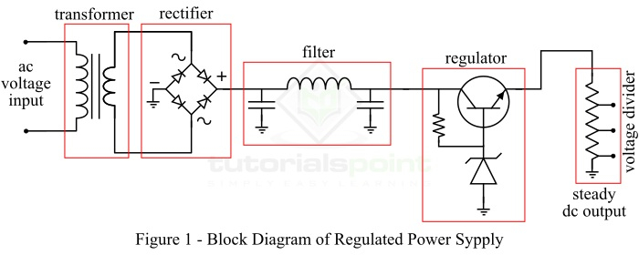
The regulated power supply consists of the following four major parts ?
- Step-down transformer
- Rectifier circuit
- DC filter circuit
- Voltage regulator
Now, let us discuss the operation of each block of the regulated power supply one by one.
Function of Step-Down Transformer
The step-down transformer used in the circuit of the regulated power supply changes the input AC voltage to the desired lower voltage value. Also, this transformer provides an electrical isolation between two circuits. The reduced output AC voltage of the step-down transformer is used as the input to the rectifier circuit.
Function of Rectifier Circuit
The rectifier circuit is used to convert the input AC voltage into a DC voltage. It consists of diodes that perform the rectification process, i.e. conversion of the AC voltage into the DC voltage. However, the output of the rectifier is a pulsating direct voltage. In practice, a full wave rectifier is used for the rectification due to its technical advantages. This full wave rectifier can be a center-tapped full-wave rectifier or a bridge rectifier. The full wave rectifier converts both positive and negative cycles of AC voltage into DC voltage.
Function of Filter Circuit
Since the output of the rectifier is a pulsating direct voltage which has very high ripple content. Hence, the raw output of the rectifier is undesirable. In order to get a pure ripple free direct voltage, a DC filter circuit is used. We have different types of filter circuits such as capacitor filter choke input filter, ?-filter, and LC filter. Therefore, the filter circuit converts the pulsating direct voltage into the constant direct voltage having almost zero ripple content.
Voltage Regulator
The voltage regulator constitutes the last block of the regulated power supply. It monitors and corrects the fluctuations in the output voltage of the power supply. The output voltage may change or fluctuate due to any change in the input AC voltage or the change in the load or change in any physical parameters such as temperature of the circuit. Thus, the voltage regulator takes care of this problem. The voltage regulator maintains the DC voltage constant at the output terminals.
A zener diode operated in zener region, a transistor series regulator, fixed and variable IC regulators are commonly used in different regulated power supplies as the voltage regulator.
Features of Regulated Power Supply
Following are the main features of the regulated power supply ?
- The regulated power supplies have the efficiency ranging from 20% to 25%.
- Regulated power supplies are relatively more reliable.
- Regulated power supplies have less complex circuit and less weight.
- Regulated power supplies give faster response.
- The cost and noise level of the regulated power supplies is low.
Applications of Regulated Power Supplies
As discussed earlier, the regulated power supplies are the embedded circuits that convert an unregulated AC power supply into a steady DC power supply which is the basic requirement of several electronic circuits. Hence, the regulated power supplies are extensively used in several applications such as ?
- Mobile charging circuits
- Testing circuits
- Bench power supplies
- Oscillators and amplifiers
- Electronic computers
- Automatic control systems, etc.
Conclusion
From the above discussion, we can conclude that a regulated power supply is an electronic circuit that converts an alternating voltage into a steady direct voltage. The regulated power supply is also known as a linear power supply.
The output of a regulated power supply does not influence from changes in the circuit condition like change in load, change in input voltage, change in component temperature, etc. Therefore, regulated power supplies are commonly used in several applications such in mobile charges, computer power supplies, testing circuits, control systems and equipment, etc.

29K+ Views
