
Article Categories
- All Categories
-
 Data Structure
-
 Networking
-
 RDBMS
RDBMS
-
 Operating System
-
 Java
Java
-
 MS Excel
-
 iOS
iOS
-
 HTML
HTML
-
 CSS
CSS
-
 Android
-
 Python
-
 C Programming
-
 C++
C++
-
 C#
C#
-
 MongoDB
-
 MySQL
MySQL
-
 Javascript
-
 PHP
PHP
-
 Economics & Finance
What is DC Voltage? – Definition, Circuit Symbol, and Wire Color Codes
In electrical and electronic circuits, the term voltagevoltage is used to denote the potential difference between two points. Based on the nature, the voltage can be of two types namely - AC Voltage and DC Voltage.
In this article, we shall confine our attention to the DC Voltage only. Here, we will discuss the definition of DC voltage, its symbolic representation, DC wire color codes used in different electrical standards, and methods of DC voltage measurement. Let?s begin with the basic definition of DC voltage.
What is DC Voltage?
DC Voltage is an abbreviation of Direct Current Voltage. The voltage which has constant polarity, i.e. always forces a current through the circuit in one direction, is known as DC Voltage.
DC voltage may be a constant DC voltage or a variable DC voltage. A constant DC voltage is one whose magnitude and polarity both remain constant, while a variable DC voltage is one whose magnitude varies with time but the polarity remains constant.
DC voltage is generally obtained from a cell, battery, or a DC generator, etc. Since the polarity of a DC voltage does not change with the time, therefore, the DC voltage has zero frequency.
DC Voltage Symbols
In electrical and electronic circuits, the symbol of dc voltage depends upon the type of source used. The symbols of a cell, a battery, and any dc voltage source are shown in figure-1.

DC Voltage Wire Color Codes
In electrical wiring, colors of wires are used to identify the polarity of the wire. Hence, the color coding makes the maintenance work easy to execute. There are mainly two color coding schemes used for DC wiring which are - IEC DC Power Circuit Wire Color Codes and US DC Power Circuit Wire Color Codes.
IEC DC Power Circuit Wire Color Codes
IEC stands for International Electrotechnical Commission. IEC defines a standard for DC power circuit wire color codes. The colors of different wires in a DC power circuit are listed in the following table ?
| DC System | Wire Name & Label | Wire Color |
|---|---|---|
| Ground or Earth | PE | Green-Yellow Strips |
| Two wire ungrounded DC circuit | Positive "L+" | Brown |
| Negative "L-" | Grey | |
| Two wire grounded DC circuit | Positive (with negative grounded) circuit "L+" | Brown |
| Negative (with negative grounded) circuit "M" | Blue | |
| Positive (with positive grounded) circuit "M" | Blue | |
| Negative (with positive grounded) circuit "L-" | Grey | |
| Three wire grounded DC circuit | Positive "L+" | Brown |
| Mid-Wire (Center tap) "M" | Blue | |
| Negative "L-" | Grey |
US DC Power Circuit Wire Color Codes
Another DC voltage wire color coding system is US National Electrical Code. It is also called NEC (National Electrical Code). This system does not define the wire color codes for ungrounded DC systems because according to US National Electrical Code, the ungrounded DC system is unsafe to use. The wire color code recommendations for DC voltage system as per the US national electrical code are listed in the following table ?
| DC System | Wire Name & Label | Wire Color |
|---|---|---|
| Protective Ground or Earth | PG | Bare conductor or Green or Green-Yellow Strips |
| Two wire ungrounded DC system | Positive "L+" | No recommendation (Red is used). |
| Negative "L-" | No recommendation (Black is used). | |
| Two wire grounded DC system | Positive (with negative grounded) circuit "L+" | Red |
| Negative (with negative grounded) circuit "N" | White | |
| Positive (with positive grounded) circuit "N" | White | |
| Negative (with positive grounded) circuit "L-" | Black | |
| Three wire grounded DC system | Positive "L+" | Red |
| Mid-wire "N" | White | |
| Negative "L-" | Black |
Methods of Reducing DC Voltage
Sometimes, we need to reduce the DC voltage before applying it across the load. For example, if we have a battery of 9 V, and an LED lamp of 3 V. In this case, we required to reduce the DC voltage so that it does not damage the LED. We can reduce the DC voltage using resistors and diodes.
Reduction of DC Voltage using Resistors
When resistors are joined in series, they form a voltage divider circuit. The voltage divider circuit splits a single DC voltage into multiple DC voltages of lower values. Using resistors connected in series, we can get any desired voltage. A typical circuit for reducing the DC voltage is shown in Figure-2.
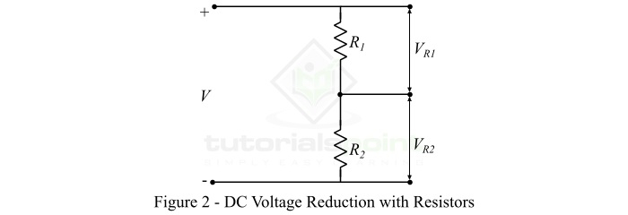
In this circuit, V is the total input voltage. The voltages across the resistance ?1 and ?2 are determined by the following expressions ?
$$\mathrm{V_{R1}=\frac{VR_{1}}{R_{1}+R_{2}}}$$
And,
$$\mathrm{V_{R2}=\frac{VR_{2}}{R_{1}+R_{2}}}$$
Hence, using these two equations, we can calculate the value of ?1 and ?2 to insert in the circuit to obtain the desired DC voltage.
Reduction of DC Voltage using Diodes
A diode is a unidirectional electronic device that conducts only when forward biased. When a diode is forward biased, some voltage drop occurs in the diode. This voltage drop in a typical silicon diode is about 0.6 V to 0.7 V, and in germanium diode is approximately 0.25 V to 0.3 V. This voltage drop can further be increased by connecting a number of diodes in series with the load as shown in Figure-3.
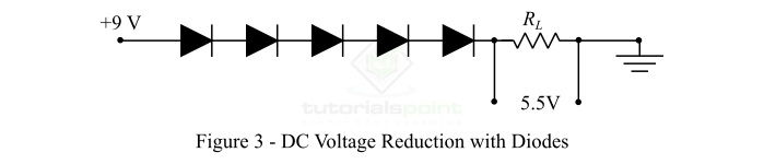
In the example shown in Figure-3, the voltage of a 9 V battery is reduced to approximately 5.5 V, and the rest 3.5 V (if each diode has 0.7 V drop) is dropped across the diodes.
How to Increase DC Voltage?
The dc voltage is increased by using an electronic circuit known as DC-DC Power Converter or Boost Converter. A typical boost converter consists of at least two semiconductor switches either diode or transistor and one energy storing element either inductor or capacitor.
Note ? There is an electronic circuit known as buck converter used to decreases the DC voltage.
Measurement of DC Voltage
The following are some common method for the measurement of DC voltage ?
DC voltage can be measured using a DC voltmeter.
We can also measure the DC voltage using a multimeter.
Sometimes, Ohm?s law is also used to calculate the DC voltage, when we have the values of circuit current and resistance.
Conclusion
In this article, we discussed all the important concepts related to the DC voltage. DC voltage is a constant polarity voltage that forces an electric current through the circuit to flow in one direction only. However, the magnitude of the DC voltage can be either constant or time varying. DC voltage is primarily used in electronic circuits. These days, a multimeter is most commonly used for the measurement of DC voltage due to its simplicity.

4K+ Views
