
 Data Structure
 Networking
 RDBMS
RDBMS Operating System
 Java
Java MS Excel
 iOS
iOS HTML
HTML CSS
CSS Android
 Python
 C Programming
 C++
C++ C#
C# MongoDB
 MySQL
MySQL Javascript
 PHP
PHP
- Selected Reading
- UPSC IAS Exams Notes
- Developer's Best Practices
- Questions and Answers
- Effective Resume Writing
- HR Interview Questions
- Computer Glossary
- Who is Who
Wait state generation in 8085 Microprocessor
The memory and the peripheral chips present today are very fast for a 8085 processor working at 3 MHz of frequency. So we do not need wait states. If we use 8085AH-2 which works at 5 MHz frequency, there we need to insert one wait state, between T2 and T3.
To D-type positive edge-triggered flip flops are used by the circuit with an active low Reset inputs. At the beginning of T1, the Address Latch Enable goes very high and causes Q1 to go high. Since Q1 and D2 are connected, D2 remains very high throughout T1. The positive edge of the clock T2 causes Q2* to become 0. We connect this to ready input of 8085. So, ready input remains 0 throughout the T2 state. So 8085 enters the Twait states instead of T3, after T2. Also, when Q2* becomes 0, Reset1* becomes 0, so we make Q1 output as 0 throughout the T2 state. The positive edge of Twait causes Q2* to become 1. This makes the input ready to 1.
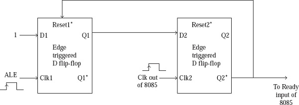
Circuit to insert a wait state between T2 and T3
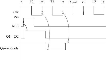
Waveforms indicating generation of wait state

2K+ Views
