
Article Categories
- All Categories
-
 Data Structure
-
 Networking
-
 RDBMS
RDBMS
-
 Operating System
-
 Java
Java
-
 MS Excel
-
 iOS
iOS
-
 HTML
HTML
-
 CSS
CSS
-
 Android
-
 Python
-
 C Programming
-
 C++
C++
-
 C#
C#
-
 MongoDB
-
 MySQL
MySQL
-
 Javascript
-
 PHP
PHP
-
 Economics & Finance
Voltage Follower using Operational Amplifier – Definition, Circuit Diagram, Working, and Applications
An electronic circuit in which the output voltage follows the input voltage is known as a voltage follower. In other words, a voltage follower is an electronic circuit whose output voltage remains the same as the input voltage. We can design a voltage follower using an operational amplifier. A voltage follower implemented using an operational amplifier is commonly known as a Unity Gain Operational Amplifier or Op-amp Buffer.
In this article, we will discuss the definition, circuit, working, advantages, and applications of a voltage follower designed using an operational amplifier. So let?s begin with the basic introduction of a voltage follower.
What is a Voltage Follower?
As discussed earlier, a voltage follower is an electronic circuit designed using an operational amplifier and has an output voltage equal to its input voltage. It is named so because its output voltages follows the input voltage.
A voltage follower is also referred to as a Buffer Amplifier, or Isolation Amplifier, or Unity Gain Amplifier. Since the voltage follower does not amplify the input voltage, its voltage gain is unity. It is mainly used to provide the buffering in the circuit.
The input impedance of a voltage follower is very high. For this reason, it is commonly used in several types of electronic circuits where an electrical isolation between the input and output is required.
Circuit Diagram and Working of Voltage Follower
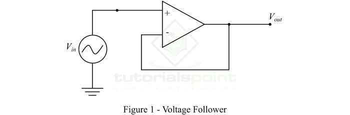
The circuit diagram of a voltage follower using an operational amplifier is shown in Figure-1.
The operation of a voltage follower is based on Ohm?s law, which is the current flowing through the circuit is equal to the ratio of its voltage to the resistance, i.e.,
$$\mathrm{Current=\frac{Voltage}{Resistance}}$$
Hence, the voltage follower is designed to have a high internal impedance (resistance). Because, the low input impedance (resistance) will cause a large amount of current to flow through the circuit for a fixed voltage. Consequently, the voltage follower takes a large amount of power from the power source causing a high source disturbances.
From the circuit diagram, it should be noted that the output of the voltage follower is connected to the inverting input terminal of the operational amplifier. Due to this connection, the operational amplifier adjusts the output voltage equal to its input voltage. Therefore, the output voltage will follow the input voltage.
Effect of High Input Impedance and Low Output Impedance
As we mentioned earlier that the voltage follower circuit has high input impedance (resistance in our case), which typically ranges from 1 M? to 10 T?.
Now, consider the input voltage is fixed and the resistance of the input and output circuits may change. Then, when the voltage follower has high input impedance, the operational amplifier does not load down the power source and draws a very small current from it.
But, we known, for a voltage follower, the input voltage and output voltage must remain the same. For this reason, the output circuit should have a very low impedance, so that the output current of the operational amplifier could be of a high value to maintain the output voltage same as the input voltage. Therefore, the voltage follower drives the load as it is driven by a perfect voltage source, but it acts as the buffer between the input and output circuits.
The use of voltage follower circuit reduces the power consumption from the source and also results in the less distortion from overloading and electromagnetic interference.
Voltage Gain of Voltage Follower
For a voltage follower, the input and output voltages are the same. Therefore, a voltage follower has a unity voltage gain. However, the voltage gain of a practical voltage follower circuit cannot be exactly unity, but it is approximately unity. In terms dB, the unit voltage gain of the voltage follower is equivalent to 0 dB.
Why Use Voltage Followers in Circuits
In electrical and electronic circuits, the voltage follower is used for the following two purposes ?
Voltage follower is used in circuits for electrical isolation between the input and output circuits.
Voltage follower is used in circuits to obtain the desired voltage at the load terminals.
Advantages of Voltage Follower
Following are the major advantages of a voltage follower ?
A voltage follower implemented using an operational amplifier takes almost zero current from the input power source.
It has high input impedance and low output impedance.
A voltage follower gives both current gain and power gain.
Voltage follower helps in avoiding the loading effect.
Voltage follower does not amplify the voltage of input signal.
Voltage follower has unity voltage gain.
Applications of Voltage Follower
Following are some important applications of voltage follower using op-amp ?
Used for isolation of input and output circuits
Used as buffer in electronic logic circuits
Used in bridge circuits through a transducer
Used in sample and hold circuits
Used in active filters
Conclusion
From the above discussion, we can conclude that a voltage follower is an operational amplifier based electronic circuit which has equal input and output voltage. It is a noninverting buffer having unity voltage gain. It is implemented using a signal operational amplifier. The use of operational amplifier in the circuit of voltage follower gives a stable unity gain.

26K+ Views
