
Article Categories
- All Categories
-
 Data Structure
-
 Networking
-
 RDBMS
RDBMS
-
 Operating System
-
 Java
Java
-
 MS Excel
-
 iOS
iOS
-
 HTML
HTML
-
 CSS
CSS
-
 Android
-
 Python
-
 C Programming
-
 C++
C++
-
 C#
C#
-
 MongoDB
-
 MySQL
MySQL
-
 Javascript
-
 PHP
PHP
-
 Economics & Finance
Selected Reading
Simulation of 4-bit ALU
Moreover, we write an assembly program in 8085 assembly language just to simulate a 4-bit ALU by using an interface which is based on the logic controller. The Arithmetic Logical Unit always performs an addition, subtraction, AND operation, or OR operation, which is based on the 4-bit inputs for the desired operations to be performed.
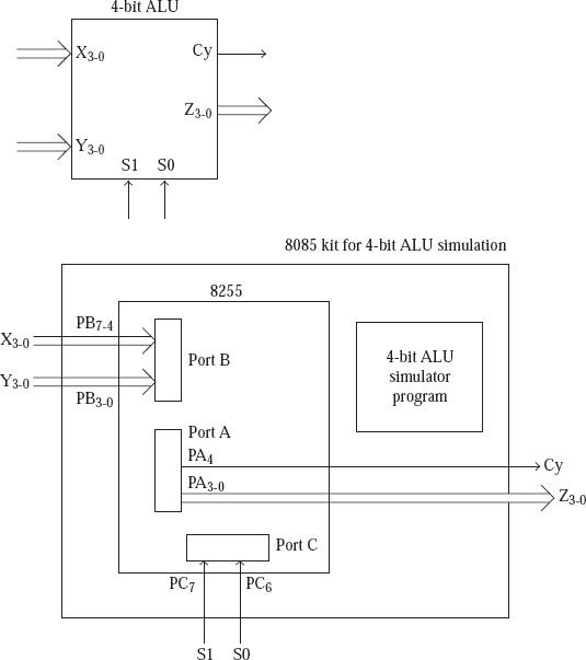
For the simulation of the Arithmetic Logical Unit all the terminal inputs and outputs are provided by the ports of 8255 as it is indicated in the figure below.
- The Pins ranging from 7-4 in the Port B are used as the inputs of X3-0;
- The pins ranging from 3-0 of Port B are used as the inputs ranging from Y3-0;
- Pins 7 and 6 of Port C used as S1 and S0 inputs;
- The port A pins of 3-0 are used as the output Z3-0;
- Pin 4 of Port A is used to provide Cy output in case of add and subtract operations.
- S1 and S0 inputs determine the operation to be performed by the ALU as per the table that follows.
|
S1 |
S0 |
Z |
|---|---|---|
| 0 |
0 |
X + Y |
| 0 |
1 |
X – Y |
| 1 |
0 |
X AND Y |
| 1 |
1 |
X OR Y |
Here S1 and S0 are the inputs and Z is the output.
Sample program code
; FILE NAME ALU_PROG1.ASM
ORG C000H
PA EQU D8H
PB EQU D9H
PC EQU DAH
CTRL EQU DBH

MVI A, 10001010B
OUT CTRL ; Configure 8255 ports
LOOP: IN PB ; Input X and Y values through Port B
MOV B, A

ANI 0FH
MOV C, A ; C will now have Y input

MOV A, B
ANI F0H
RRC
RRC
RRC
RRC
MOV B, A ; B will now have X input

IN PC ; Read S1 and S0 values from Port
ANI 11000000B

RLC
RLC ; LS 2 bits of A will now have S1 and S0

CPI 00H
JZ ADD ; If S1 = 0 and S0 = 0 do Add operation

CPI 01H
JZ SUB ; If S1 = 0 and S0 = 1 do Subtract operation

CPI 02H
JZ AND ; If S1 = 1 and S0 = 0 do AND operation
OR: MOV A, B
ORA C
JMP DISP

ADD: MOV A, B
ADD C
JMP DISP

SUB: MOV A, B
SUB C
JMP DISP

AND: MOV A, B
ANA C
DISP: OUT PA
JMP LOOP

Updated on: 2019-07-30T22:30:25+05:30
2K+ Views

Advertisements