 Data Structure
 Networking
 RDBMS
RDBMS Operating System
 Java
Java MS Excel
 iOS
iOS HTML
HTML CSS
CSS Android
 Python
 C Programming
 C++
C++ C#
C# MongoDB
 MySQL
MySQL Javascript
 PHP
PHP
- Selected Reading
- UPSC IAS Exams Notes
- Developer's Best Practices
- Questions and Answers
- Effective Resume Writing
- HR Interview Questions
- Computer Glossary
- Who is Who
Routing within a datagram network
In packet switching networks using datagrams, datagrams are data packets which contain adequate header information so that they can be individually routed by all intermediate switching devices to the destination. These networks are called datagram networks since communication occurs via datagrams.
Routing Principle
In datagram networks, each data packet is routed independently from the source to the destination even if they belong to the same message. No prior resource or channel allocation is done for the individual packets. As the datagrams are treated as independent units, no dedicated path is fixed for data transfer. Each datagram is routed by the intermediate routers using dynamically changing routing tables. So two successive packets from the source may follow completely separate routes to reach destination. Resources are allocated on demand on a First-Come First-Serve (FCFS) basis. When a packet arrives at a router, the packet must wait if there are other packets being processed, irrespective of its source or destination.
Example of Routing in a Datagram Network
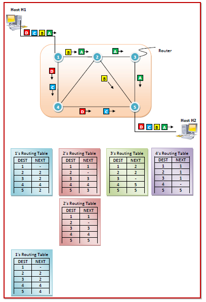
The diagram below shows a message being send by host H1 to host H2. The Internet Service Provider (ISP) comprises of five routers that are numbered from 1 to 5. H1 is connected to router 1 while H2 is connected to router 5.
Suppose that the message is of such a size that it has to be broken into 4 packets. The packets are labelled as A, B, C and D.
Each of the five routers maintains a routing table that has two columns, DEST storing the destination node and NEXT storing next node. To reach the DEST node the packet is routed via the NEXT node. The routing tables are dynamic in nature that are refreshed time to time depending upon the network conditions.

When packet A is to be transmitted, it is transferred to router 1 by host H1. The destination is router 5, since host H2 is connected to it. Router 1 consults its routing table (the one in the top row) and sends the packet to router 2. Router 2 sends it to router 3 which sends it to router 5.
So, the path of packet A is 1 − 2 − 3 − 5.
When packet B is to be transmitted, the routing table of router 2 has changed. Consequently, the path of packet B is different from that of A.
The path of packet B is 1 − 2 − 5.
When packet C is to be transmitted, the routing table of router 1 has changed.
Thus, the path of packet C is 1 − 4 − 5.
The routing tables remain same for the next packet. So, the path doesn’t change for it.
Hence, the path of packet D is again 1 − 4 − 5.

