
Article Categories
- All Categories
-
 Data Structure
-
 Networking
-
 RDBMS
RDBMS
-
 Operating System
-
 Java
Java
-
 MS Excel
-
 iOS
iOS
-
 HTML
HTML
-
 CSS
CSS
-
 Android
-
 Python
-
 C Programming
-
 C++
C++
-
 C#
C#
-
 MongoDB
-
 MySQL
MySQL
-
 Javascript
-
 PHP
PHP
-
 Economics & Finance
Resistor Types and Color Code
Resistor
The measure of opposition offered by the substance in the flow electric current is known as Resistance of the substance and the element that possess the resistance is called a Resistor. The circuit symbol of resistor is shown in the figure below.

Types of Resistors
The resistor are broadly classified into two types –
Fixed Resistors
Variable Resistors
Fixed Resistors
The fixed resistor is defined as the resistor whose resistance value does not change with the any change in temperature or voltage. These resistors are available in different shapes and sizes. The main function of an ideal fixed resistance gives a stable resistance in all situations. The fixed resistor has two terminals which are used for connecting it in the circuit.
There are various types of fixed resistors as follow −
Carbon Composition Resistor
Metal Film Resistor
Surface Mount Resistor
Thick Film Resistor
Thin Film Resistor
Wire Wound Resistor
Carbon Composition Resistor
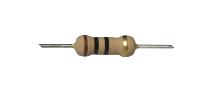
The carbon composition resistor (also known as Carbon Resistor) is a type of fixed resistor that control the electric current flow to a certain level in a circuit. The carbon composition resistors are made from a solid cylindrical resistive element with embedded metal wire leads. The resistive element of the carbon composition resistor is made up of the mixture of graphite powder and ceramic. The cylindrical resistive element is covered with plastic to protect the resistor from outside damages. The carbon composition resistors are available in the resistance values ranging from 1 Ω to 22 MΩ.
Metal Film Resistor
The metal film resistors are made up of metal oxide or rods of metals coated with ceramic. The resistance value of these resistors is controlled by the thickness of coating layer. These resistances are more reliable, stable and accurate as compared to carbon resistors. The metal film resistors are available in a wide range of resistance values ranging from a few ohms to millions of ohms.
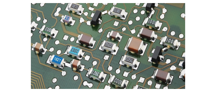
Surface Mount (SMD) Resistors
The SMD resistors are made by depositing a film of resistive material. These resistors are available in different shapes and sizes agreed by the Electronics Industry Alliance (EIA). Since the size of these resistors is very small, hence does not have enough space for color code bands. The number codes printed on these resistors work in a similar manner as the color bands on the carbon resistors.
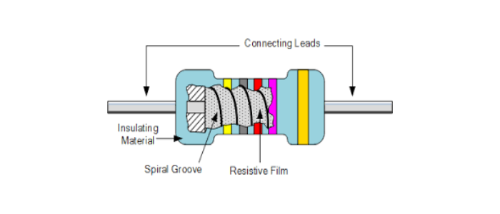
Thin Film Resistor
The thin film resistor is made by depositing a resistance material on an insulating material (glass or ceramic) substrate. In order to deposit thin film on the substrate a photographic process is used. The metal leads with caps are fitted over each end of the substrate to make the body of the resistor. This type of resistors is usually a small wattage and fixed value resistor. The advantage of thin film is smaller component.
Thick Film Resistor
The thick film resistors are made by depositing a special resistive paste directly on the insulated substrate by using stencil screen process. The thick film is a thicker deposit of resistive material as compared to thin film. The advantage of thick film is the component can with stand with high wattage and currents.
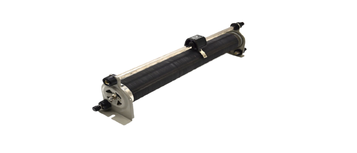
Wire Wound Resistor
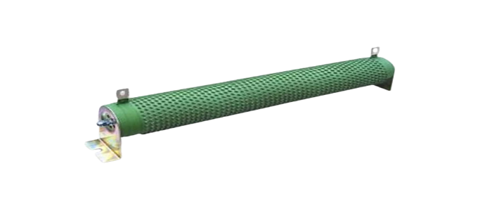
The wire wound resistors, as name implies, are made by winding a thin wire on a ceramic core. The whole component is insulated by a coating of opaque enamel. These types of resistors having excellent properties such as low resistive values and high power ratings. These type of resistors are used in high current applications.
Variable Resistors
The variable resistors consist of a fixed value resistance between two terminals. It is also a wire wound resistor. These resistors has two fixed terminals and moving terminal or sliding tap. The variable resistor is not entirely covered by enamel material. Instead, some portion of the wire is exposed. By adjusting the sliding tap across the exposed surface various resistance values can be obtained in the circuit.
Types of Variable Resistors −
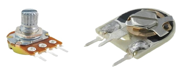
Potentiometer
Rheostat
Thermistor
Light Dependent Resistor (LDR)
Varistor
Magneto Resistor
Potentiometer or Preset
The potentiometer and preset are most commonly used variable resistors. These resistors consist of a fixed value of resistance between two terminals and have a rotary knob that changes the resistance value as it is turned. The variation in the resistance is provided by a contact that is attached to a resistive material inside the equipment.
Rheostat
A rheostat is also a variable resistor which is used to control current in the circuit. The construction of rheostat is similar to that of a potentiometer. It uses only two terminals instead of three terminal as in a potentiometer. The first connection is made to one end of resistive element and the other connection to the slider contact. These are also a wire wound resistors in which the resistive wire is wound around a ceramic core and the sliding contact placed over the winding.
Thermistor
The thermistor is a special type of resistors whose resistive value change rapidly as its temperature changes. It is commonly used in the application like to prevent the inrush currents in electrical circuits.

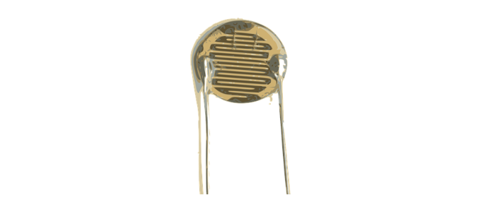
Light Dependent Resistor (LDR)
An LDR is a variable resistor whose resistive value is a function of light i.e. when the resistor is in darkness, its resistance is very high of the order of 1 MΩ while when the light falls on it, the falls down to a few kΩ.
Varistor
A varistor is also a variable resistor whose resistive value changes according to the applied voltage. This resistor is also known as Voltage Dependent Resistor (VDR). It has non ohmic characteristics, hence it is a non-linear resistor.
Magneto Resistor
A resistor whose resistance changes according to the external magnetic field applied to it, is known as magneto resistor. It is also known as Magnetic Dependent Resistor (MDR). These resistors are used to measure presence, direction and strength of magnetic field.
Resistor Color Code
The values of resistors are determined by color band marked on the resistor body. The color code marking system has been adopted by the Electronics Industries Association (EIA) and the United States Armed Forces and recognized throughout the world.
Resistor Color Code Table
| Color | 1st Band | 2nd Band | 3rd Band | Multiplier | Tolerance(%) |
|---|---|---|---|---|---|
| Black | 0 | 0 | 0 | × 100 | |
| Brown | 1 | 1 | 1 | × 101 | ±1 |
| Red | 2 | 2 | 2 | × 102 | ±2 |
| Orange | 3 | 3 | 3 | × 103 | |
| Yellow | 4 | 4 | 4 | × 104 | |
| Green | 5 | 5 | 5 | × 105 | ±0.5 |
| Sky-blue | 6 | 6 | 6 | × 106 | ±0.25 |
| Violet | 7 | 7 | 7 | × 107 | ±0.1 |
| Grey | 8 | 8 | 8 | × 108 | |
| White | 9 | 9 | 9 | × 109 | |
| Gold | × 10-1 | ±5 | |||
| Sliver | × 10-2 | ±10 | |||
| None | ±20 |
Resistor Color Code Calculation

1st Band – Red – Band Value from the Table =2
2nd Band – Yellow – Band Value = 4
3rd Band – Green – Band Value = 5
Multiplier – Violet – Band Value = × 107
Tolerance – Gold – Band Value = ± 5 %
Hence the resistance value will be,
R=245×107±5 %

5K+ Views
