- Home
- Introduction
- Convergence of Parallel Architectures
- Parallel Computer Models
- Processor in Parallel Systems
- Multiprocessors and Multicomputers
- Cache Coherence & Synchronization
- Hardware-Software Tradeoffs
- Interconnection Network Design
- Latency Tolerance
Parallel Computer Architecture - Quick Guide
Parallel Computer Architecture - Introduction
In the last 50 years, there has been huge developments in the performance and capability of a computer system. This has been possible with the help of Very Large Scale Integration (VLSI) technology. VLSI technology allows a large number of components to be accommodated on a single chip and clock rates to increase. Therefore, more operations can be performed at a time, in parallel.
Parallel processing is also associated with data locality and data communication. Parallel Computer Architecture is the method of organizing all the resources to maximize the performance and the programmability within the limits given by technology and the cost at any instance of time.
Why Parallel Architecture?
Parallel computer architecture adds a new dimension in the development of computer system by using more and more number of processors. In principle, performance achieved by utilizing large number of processors is higher than the performance of a single processor at a given point of time.
Application Trends
With the advancement of hardware capacity, the demand for a well-performing application also increased, which in turn placed a demand on the development of the computer architecture.
Before the microprocessor era, high-performing computer system was obtained by exotic circuit technology and machine organization, which made them expensive. Now, highly performing computer system is obtained by using multiple processors, and most important and demanding applications are written as parallel programs. Thus, for higher performance both parallel architectures and parallel applications are needed to be developed.
To increase the performance of an application Speedup is the key factor to be considered. Speedup on p processors is defined as −
$$Speedup(p \ processors)\equiv\frac{Performance(p \ processors)}{Performance(1 \ processor)}$$For the single fixed problem,
$$performance \ of \ a \ computer \ system = \frac{1}{Time \ needed \ to \ complete \ the \ problem}$$ $$Speedup \ _{fixed \ problem} (p \ processors) =\frac{Time(1 \ processor)}{Time(p \ processor)}$$Scientific and Engineering Computing
Parallel architecture has become indispensable in scientific computing (like physics, chemistry, biology, astronomy, etc.) and engineering applications (like reservoir modeling, airflow analysis, combustion efficiency, etc.). In almost all applications, there is a huge demand for visualization of computational output resulting in the demand for development of parallel computing to increase the computational speed.
Commercial Computing
In commercial computing (like video, graphics, databases, OLTP, etc.) also high speed computers are needed to process huge amount of data within a specified time. Desktop uses multithreaded programs that are almost like the parallel programs. This in turn demands to develop parallel architecture.
Technology Trends
With the development of technology and architecture, there is a strong demand for the development of high-performing applications. Experiments show that parallel computers can work much faster than utmost developed single processor. Moreover, parallel computers can be developed within the limit of technology and the cost.
The primary technology used here is VLSI technology. Therefore, nowadays more and more transistors, gates and circuits can be fitted in the same area. With the reduction of the basic VLSI feature size, clock rate also improves in proportion to it, while the number of transistors grows as the square. The use of many transistors at once (parallelism) can be expected to perform much better than by increasing the clock rate
Technology trends suggest that the basic single chip building block will give increasingly large capacity. Therefore, the possibility of placing multiple processors on a single chip increases.
Architectural Trends
Development in technology decides what is feasible; architecture converts the potential of the technology into performance and capability. Parallelism and locality are two methods where larger volumes of resources and more transistors enhance the performance. However, these two methods compete for the same resources. When multiple operations are executed in parallel, the number of cycles needed to execute the program is reduced.
However, resources are needed to support each of the concurrent activities. Resources are also needed to allocate local storage. The best performance is achieved by an intermediate action plan that uses resources to utilize a degree of parallelism and a degree of locality.
Generally, the history of computer architecture has been divided into four generations having following basic technologies −
- Vacuum tubes
- Transistors
- Integrated circuits
- VLSI
Till 1985, the duration was dominated by the growth in bit-level parallelism. 4-bit microprocessors followed by 8-bit, 16-bit, and so on. To reduce the number of cycles needed to perform a full 32-bit operation, the width of the data path was doubled. Later on, 64-bit operations were introduced.
The growth in instruction-level-parallelism dominated the mid-80s to mid-90s. The RISC approach showed that it was simple to pipeline the steps of instruction processing so that on an average an instruction is executed in almost every cycle. Growth in compiler technology has made instruction pipelines more productive.
In mid-80s, microprocessor-based computers consisted of
- An integer processing unit
- A floating-point unit
- A cache controller
- SRAMs for the cache data
- Tag storage
As chip capacity increased, all these components were merged into a single chip. Thus, a single chip consisted of separate hardware for integer arithmetic, floating point operations, memory operations and branch operations. Other than pipelining individual instructions, it fetches multiple instructions at a time and sends them in parallel to different functional units whenever possible. This type of instruction level parallelism is called superscalar execution.
Convergence of Parallel Architectures
Parallel machines have been developed with several distinct architecture. In this section, we will discuss different parallel computer architecture and the nature of their convergence.
Communication Architecture
Parallel architecture enhances the conventional concepts of computer architecture with communication architecture. Computer architecture defines critical abstractions (like user-system boundary and hardware-software boundary) and organizational structure, whereas communication architecture defines the basic communication and synchronization operations. It also addresses the organizational structure.
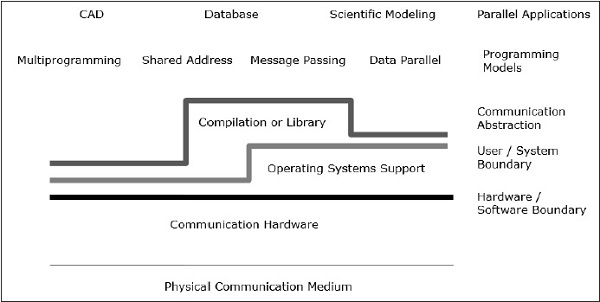
Programming model is the top layer. Applications are written in programming model. Parallel programming models include −
- Shared address space
- Message passing
- Data parallel programming
Shared address programming is just like using a bulletin board, where one can communicate with one or many individuals by posting information at a particular location, which is shared by all other individuals. Individual activity is coordinated by noting who is doing what task.
Message passing is like a telephone call or letters where a specific receiver receives information from a specific sender.
Data parallel programming is an organized form of cooperation. Here, several individuals perform an action on separate elements of a data set concurrently and share information globally.
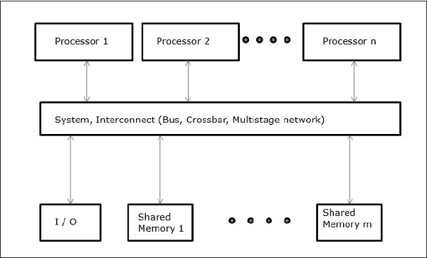
Shared Memory
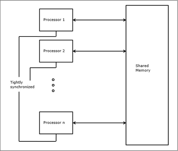
Shared memory multiprocessors are one of the most important classes of parallel machines. It gives better throughput on multiprogramming workloads and supports parallel programs.
In this case, all the computer systems allow a processor and a set of I/O controller to access a collection of memory modules by some hardware interconnection. The memory capacity is increased by adding memory modules and I/O capacity is increased by adding devices to I/O controller or by adding additional I/O controller. Processing capacity can be increased by waiting for a faster processor to be available or by adding more processors.
All the resources are organized around a central memory bus. Through the bus access mechanism, any processor can access any physical address in the system. As all the processors are equidistant from all the memory locations, the access time or latency of all the processors is same on a memory location. This is called symmetric multiprocessor.
Message-Passing Architecture
Message passing architecture is also an important class of parallel machines. It provides communication among processors as explicit I/O operations. In this case, the communication is combined at the I/O level, instead of the memory system.
In message passing architecture, user communication executed by using operating system or library calls that perform many lower level actions, which includes the actual communication operation. As a result, there is a distance between the programming model and the communication operations at the physical hardware level.
Send and receive is the most common user level communication operations in message passing system. Send specifies a local data buffer (which is to be transmitted) and a receiving remote processor. Receive specifies a sending process and a local data buffer in which the transmitted data will be placed. In send operation, an identifier or a tag is attached to the message and the receiving operation specifies the matching rule like a specific tag from a specific processor or any tag from any processor.
The combination of a send and a matching receive completes a memory-to-memory copy. Each end specifies its local data address and a pair wise synchronization event.
Convergence
Development of the hardware and software has faded the clear boundary between the shared memory and message passing camps. Message passing and a shared address space represents two distinct programming models; each gives a transparent paradigm for sharing, synchronization and communication. However, the basic machine structures have converged towards a common organization.
Data Parallel Processing
Another important class of parallel machine is variously called − processor arrays, data parallel architecture and single-instruction-multiple-data machines. The main feature of the programming model is that operations can be executed in parallel on each element of a large regular data structure (like array or matrix).
Data parallel programming languages are usually enforced by viewing the local address space of a group of processes, one per processor, forming an explicit global space. As all the processors communicate together and there is a global view of all the operations, so either a shared address space or message passing can be used.
Fundamental Design Issues
Development of programming model only cannot increase the efficiency of the computer nor can the development of hardware alone do it. However, development in computer architecture can make the difference in the performance of the computer. We can understand the design problem by focusing on how programs use a machine and which basic technologies are provided.
In this section, we will discuss about the communication abstraction and the basic requirements of the programming model.
Communication Abstraction
Communication abstraction is the main interface between the programming model and the system implementation. It is like the instruction set that provides a platform so that the same program can run correctly on many implementations. Operations at this level must be simple.
Communication abstraction is like a contract between the hardware and software, which allows each other the flexibility to improve without affecting the work.
Programming Model Requirements
A parallel program has one or more threads operating on data. A parallel programming model defines what data the threads can name, which operations can be performed on the named data, and which order is followed by the operations.
To confirm that the dependencies between the programs are enforced, a parallel program must coordinate the activity of its threads.
Parallel Computer Architecture - Models
Parallel processing has been developed as an effective technology in modern computers to meet the demand for higher performance, lower cost and accurate results in real-life applications. Concurrent events are common in todays computers due to the practice of multiprogramming, multiprocessing, or multicomputing.
Modern computers have powerful and extensive software packages. To analyze the development of the performance of computers, first we have to understand the basic development of hardware and software.
Computer Development Milestones − There is two major stages of development of computer - mechanical or electromechanical parts. Modern computers evolved after the introduction of electronic components. High mobility electrons in electronic computers replaced the operational parts in mechanical computers. For information transmission, electric signal which travels almost at the speed of a light replaced mechanical gears or levers.
Elements of Modern computers − A modern computer system consists of computer hardware, instruction sets, application programs, system software and user interface.
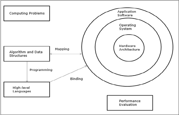
The computing problems are categorized as numerical computing, logical reasoning, and transaction processing. Some complex problems may need the combination of all the three processing modes.
Evolution of Computer Architecture − In last four decades, computer architecture has gone through revolutionary changes. We started with Von Neumann architecture and now we have multicomputers and multiprocessors.
Performance of a computer system − Performance of a computer system depends both on machine capability and program behavior. Machine capability can be improved with better hardware technology, advanced architectural features and efficient resource management. Program behavior is unpredictable as it is dependent on application and run-time conditions
Multiprocessors and Multicomputers
In this section, we will discuss two types of parallel computers −
- Multiprocessors
- Multicomputers
Shared-Memory Multicomputers
Three most common shared memory multiprocessors models are −
Uniform Memory Access (UMA)
In this model, all the processors share the physical memory uniformly. All the processors have equal access time to all the memory words. Each processor may have a private cache memory. Same rule is followed for peripheral devices.
When all the processors have equal access to all the peripheral devices, the system is called a symmetric multiprocessor. When only one or a few processors can access the peripheral devices, the system is called an asymmetric multiprocessor.
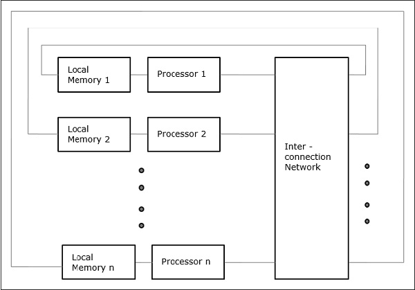
Non-uniform Memory Access (NUMA)
In NUMA multiprocessor model, the access time varies with the location of the memory word. Here, the shared memory is physically distributed among all the processors, called local memories. The collection of all local memories forms a global address space which can be accessed by all the processors.
Cache Only Memory Architecture (COMA)
The COMA model is a special case of the NUMA model. Here, all the distributed main memories are converted to cache memories.
Distributed - Memory Multicomputers − A distributed memory multicomputer system consists of multiple computers, known as nodes, inter-connected by message passing network. Each node acts as an autonomous computer having a processor, a local memory and sometimes I/O devices. In this case, all local memories are private and are accessible only to the local processors. This is why, the traditional machines are called no-remote-memory-access (NORMA) machines.
Multivector and SIMD Computers
In this section, we will discuss supercomputers and parallel processors for vector processing and data parallelism.
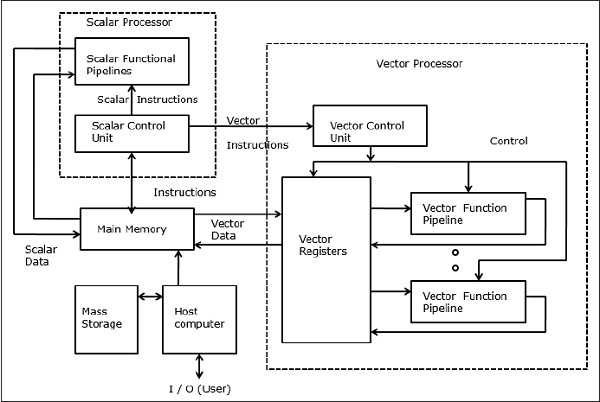
Vector Supercomputers
In a vector computer, a vector processor is attached to the scalar processor as an optional feature. The host computer first loads program and data to the main memory. Then the scalar control unit decodes all the instructions. If the decoded instructions are scalar operations or program operations, the scalar processor executes those operations using scalar functional pipelines.
On the other hand, if the decoded instructions are vector operations then the instructions will be sent to vector control unit.
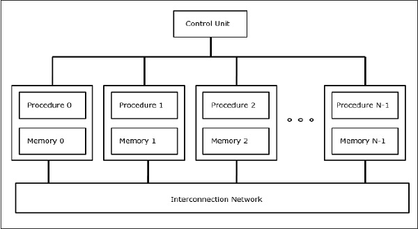
SIMD Supercomputers
In SIMD computers, N number of processors are connected to a control unit and all the processors have their individual memory units. All the processors are connected by an interconnection network.
PRAM and VLSI Models
The ideal model gives a suitable framework for developing parallel algorithms without considering the physical constraints or implementation details.
The models can be enforced to obtain theoretical performance bounds on parallel computers or to evaluate VLSI complexity on chip area and operational time before the chip is fabricated.
Parallel Random-Access Machines
Sheperdson and Sturgis (1963) modeled the conventional Uniprocessor computers as random-access-machines (RAM). Fortune and Wyllie (1978) developed a parallel random-access-machine (PRAM) model for modeling an idealized parallel computer with zero memory access overhead and synchronization.
An N-processor PRAM has a shared memory unit. This shared memory can be centralized or distributed among the processors. These processors operate on a synchronized read-memory, write-memory and compute cycle. So, these models specify how concurrent read and write operations are handled.
Following are the possible memory update operations −
Exclusive read (ER) − In this method, in each cycle only one processor is allowed to read from any memory location.
Exclusive write (EW) − In this method, at least one processor is allowed to write into a memory location at a time.
Concurrent read (CR) − It allows multiple processors to read the same information from the same memory location in the same cycle.
Concurrent write (CW) − It allows simultaneous write operations to the same memory location. To avoid write conflict some policies are set up.
VLSI Complexity Model
Parallel computers use VLSI chips to fabricate processor arrays, memory arrays and large-scale switching networks.
Nowadays, VLSI technologies are 2-dimensional. The size of a VLSI chip is proportional to the amount of storage (memory) space available in that chip.
We can calculate the space complexity of an algorithm by the chip area (A) of the VLSI chip implementation of that algorithm. If T is the time (latency) needed to execute the algorithm, then A.T gives an upper bound on the total number of bits processed through the chip (or I/O). For certain computing, there exists a lower bound, f(s), such that
A.T2 >= O (f(s))
Where A=chip area and T=time
Architectural Development Tracks
The evolution of parallel computers I spread along the following tracks −
- Multiple Processor Tracks
- Multiprocessor track
- Multicomputer track
- Multiple data track
- Vector track
- SIMD track
- Multiple threads track
- Multithreaded track
- Dataflow track
In multiple processor track, it is assumed that different threads execute concurrently on different processors and communicate through shared memory (multiprocessor track) or message passing (multicomputer track) system.
In multiple data track, it is assumed that the same code is executed on the massive amount of data. It is done by executing same instructions on a sequence of data elements (vector track) or through the execution of same sequence of instructions on a similar set of data (SIMD track).
In multiple threads track, it is assumed that the interleaved execution of various threads on the same processor to hide synchronization delays among threads executing on different processors. Thread interleaving can be coarse (multithreaded track) or fine (dataflow track).
Processor in Parallel Systems
In the 80s, a special purpose processor was popular for making multicomputers called Transputer. A transputer consisted of one core processor, a small SRAM memory, a DRAM main memory interface and four communication channels, all on a single chip. To make a parallel computer communication, channels were connected to form a network of Transputers. But it has a lack of computational power and hence couldnt meet the increasing demand of parallel applications. This problem was solved by the development of RISC processors and it was cheap also.
Modern parallel computer uses microprocessors which use parallelism at several levels like instruction-level parallelism and data level parallelism.
High Performance Processors
RISC and RISCy processors dominate todays parallel computers market.
Characteristics of traditional RISC are −
- Has few addressing modes.
- Has a fixed format for instructions, usually 32 or 64 bits.
- Has dedicated load/store instructions to load data from memory to register and store data from register to memory.
- Arithmetic operations are always performed on registers.
- Uses pipelining.
Most of the microprocessors these days are superscalar, i.e. in a parallel computer multiple instruction pipelines are used. Therefore, superscalar processors can execute more than one instruction at the same time. Effectiveness of superscalar processors is dependent on the amount of instruction-level parallelism (ILP) available in the applications. To keep the pipelines filled, the instructions at the hardware level are executed in a different order than the program order.
Many modern microprocessors use super pipelining approach. In super pipelining, to increase the clock frequency, the work done within a pipeline stage is reduced and the number of pipeline stages is increased.
Very Large Instruction Word (VLIW) Processors
These are derived from horizontal microprogramming and superscalar processing. Instructions in VLIW processors are very large. The operations within a single instruction are executed in parallel and are forwarded to the appropriate functional units for execution. So, after fetching a VLIW instruction, its operations are decoded. Then the operations are dispatched to the functional units in which they are executed in parallel.
Vector Processors
Vector processors are co-processor to general-purpose microprocessor. Vector processors are generally register-register or memory-memory. A vector instruction is fetched and decoded and then a certain operation is performed for each element of the operand vectors, whereas in a normal processor a vector operation needs a loop structure in the code. To make it more efficient, vector processors chain several vector operations together, i.e., the result from one vector operation are forwarded to another as operand.
Caching
Caches are important element of high-performance microprocessors. After every 18 months, speed of microprocessors become twice, but DRAM chips for main memory cannot compete with this speed. So, caches are introduced to bridge the speed gap between the processor and memory. A cache is a fast and small SRAM memory. Many more caches are applied in modern processors like Translation Look-aside Buffers (TLBs) caches, instruction and data caches, etc.
Direct Mapped Cache
In direct mapped caches, a modulo function is used for one-to-one mapping of addresses in the main memory to cache locations. As same cache entry can have multiple main memory blocks mapped to it, the processor must be able to determine whether a data block in the cache is the data block that is actually needed. This identification is done by storing a tag together with a cache block.
Fully Associative Cache
A fully associative mapping allows for placing a cache block anywhere in the cache. By using some replacement policy, the cache determines a cache entry in which it stores a cache block. Fully associative caches have flexible mapping, which minimizes the number of cache-entry conflicts. Since a fully associative implementation is expensive, these are never used large scale.
Set-associative Cache
A set-associative mapping is a combination of a direct mapping and a fully associative mapping. In this case, the cache entries are subdivided into cache sets. As in direct mapping, there is a fixed mapping of memory blocks to a set in the cache. But inside a cache set, a memory block is mapped in a fully associative manner.
Cache strategies
Other than mapping mechanism, caches also need a range of strategies that specify what should happen in the case of certain events. In case of (set-) associative caches, the cache must determine which cache block is to be replaced by a new block entering the cache.
Some well-known replacement strategies are −
- First-In First Out (FIFO)
- Least Recently Used (LRU)
Multiprocessors and Multicomputers
We will discuss multiprocessors and multicomputers in this chapter.
Multiprocessor System Interconnects
Parallel processing needs the use of efficient system interconnects for fast communication among the Input/Output and peripheral devices, multiprocessors and shared memory.
Hierarchical Bus Systems
A hierarchical bus system consists of a hierarchy of buses connecting various systems and sub-systems/components in a computer. Each bus is made up of a number of signal, control, and power lines. Different buses like local buses, backplane buses and I/O buses are used to perform different interconnection functions.
Local buses are the buses implemented on the printed-circuit boards. A backplane bus is a printed circuit on which many connectors are used to plug in functional boards. Buses which connect input/output devices to a computer system are known as I/O buses.
Crossbar switch and Multiport Memory
Switched networks give dynamic interconnections among the inputs and outputs. Small or medium size systems mostly use crossbar networks. Multistage networks can be expanded to the larger systems, if the increased latency problem can be solved.
Both crossbar switch and multiport memory organization is a single-stage network. Though a single stage network is cheaper to build, but multiple passes may be needed to establish certain connections. A multistage network has more than one stage of switch boxes. These networks should be able to connect any input to any output.
Multistage and Combining Networks
Multistage networks or multistage interconnection networks are a class of high-speed computer networks which is mainly composed of processing elements on one end of the network and memory elements on the other end, connected by switching elements.
These networks are applied to build larger multiprocessor systems. This includes Omega Network, Butterfly Network and many more.
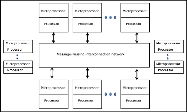
Multicomputers
Multicomputers are distributed memory MIMD architectures. The following diagram shows a conceptual model of a multicomputer −
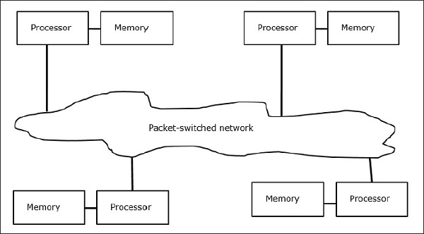
Multicomputers are message-passing machines which apply packet switching method to exchange data. Here, each processor has a private memory, but no global address space as a processor can access only its own local memory. So, communication is not transparent: here programmers have to explicitly put communication primitives in their code.
Having no globally accessible memory is a drawback of multicomputers. This can be solved by using the following two schemes −
- Virtual Shared Memory (VSM)
- Shared Virtual Memory (SVM)
In these schemes, the application programmer assumes a big shared memory which is globally addressable. If required, the memory references made by applications are translated into the message-passing paradigm.
Virtual Shared Memory (VSM)
VSM is a hardware implementation. So, the virtual memory system of the Operating System is transparently implemented on top of VSM. So, the operating system thinks it is running on a machine with a shared memory.
Shared Virtual Memory (SVM)
SVM is a software implementation at the Operating System level with hardware support from the Memory Management Unit (MMU) of the processor. Here, the unit of sharing is Operating System memory pages.
If a processor addresses a particular memory location, the MMU determines whether the memory page associated with the memory access is in the local memory or not. If the page is not in the memory, in a normal computer system it is swapped in from the disk by the Operating System. But, in SVM, the Operating System fetches the page from the remote node which owns that particular page.
Three Generations of Multicomputers
In this section, we will discuss three generations of multicomputers.
Design Choices in the Past
While selecting a processor technology, a multicomputer designer chooses low-cost medium grain processors as building blocks. Majority of parallel computers are built with standard off-the-shelf microprocessors. Distributed memory was chosen for multi-computers rather than using shared memory, which would limit the scalability. Each processor has its own local memory unit.
For interconnection scheme, multicomputers have message passing, point-to-point direct networks rather than address switching networks. For control strategy, designer of multi-computers choose the asynchronous MIMD, MPMD, and SMPD operations. Caltechs Cosmic Cube (Seitz, 1983) is the first of the first generation multi-computers.
Present and Future Development
The next generation computers evolved from medium to fine grain multicomputers using a globally shared virtual memory. Second generation multi-computers are still in use at present. But using better processor like i386, i860, etc. second generation computers have developed a lot.
Third generation computers are the next generation computers where VLSI implemented nodes will be used. Each node may have a 14-MIPS processor, 20-Mbytes/s routing channels and 16 Kbytes of RAM integrated on a single chip.
The Intel Paragon System
Previously, homogeneous nodes were used to make hypercube multicomputers, as all the functions were given to the host. So, this limited the I/O bandwidth. Thus to solve large-scale problems efficiently or with high throughput, these computers could not be used.The Intel Paragon System was designed to overcome this difficulty. It turned the multicomputer into an application server with multiuser access in a network environment.
Message Passing Mechanisms
Message passing mechanisms in a multicomputer network needs special hardware and software support. In this section, we will discuss some schemes.
Message-Routing Schemes
In multicomputer with store and forward routing scheme, packets are the smallest unit of information transmission. In wormholerouted networks, packets are further divided into flits. Packet length is determined by the routing scheme and network implementation, whereas the flit length is affected by the network size.
In Store and forward routing, packets are the basic unit of information transmission. In this case, each node uses a packet buffer. A packet is transmitted from a source node to a destination node through a sequence of intermediate nodes. Latency is directly proportional to the distance between the source and the destination.
In wormhole routing, the transmission from the source node to the destination node is done through a sequence of routers. All the flits of the same packet are transmitted in an inseparable sequence in a pipelined fashion. In this case, only the header flit knows where the packet is going.
Deadlock and Virtual Channels
A virtual channel is a logical link between two nodes. It is formed by flit buffer in source node and receiver node, and a physical channel between them. When a physical channel is allocated for a pair, one source buffer is paired with one receiver buffer to form a virtual channel.
When all the channels are occupied by messages and none of the channel in the cycle is freed, a deadlock situation will occur. To avoid this a deadlock avoidance scheme has to be followed.
Cache Coherence and Synchronization
In this chapter, we will discuss the cache coherence protocols to cope with the multicache inconsistency problems.
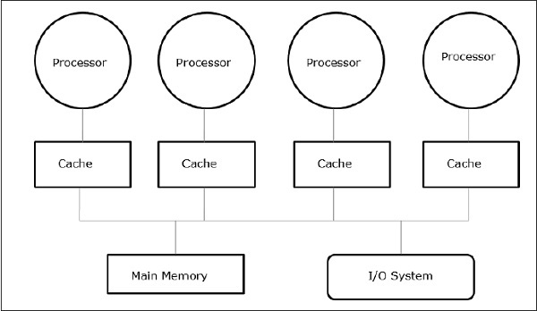
The Cache Coherence Problem
In a multiprocessor system, data inconsistency may occur among adjacent levels or within the same level of the memory hierarchy. For example, the cache and the main memory may have inconsistent copies of the same object.
As multiple processors operate in parallel, and independently multiple caches may possess different copies of the same memory block, this creates cache coherence problem. Cache coherence schemes help to avoid this problem by maintaining a uniform state for each cached block of data.
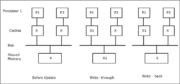
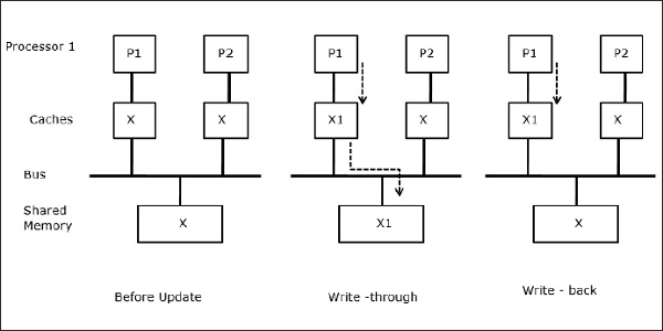
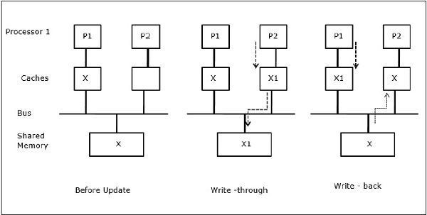
Let X be an element of shared data which has been referenced by two processors, P1 and P2. In the beginning, three copies of X are consistent. If the processor P1 writes a new data X1 into the cache, by using write-through policy, the same copy will be written immediately into the shared memory. In this case, inconsistency occurs between cache memory and the main memory. When a write-back policy is used, the main memory will be updated when the modified data in the cache is replaced or invalidated.
In general, there are three sources of inconsistency problem −
- Sharing of writable data
- Process migration
- I/O activity
Snoopy Bus Protocols
Snoopy protocols achieve data consistency between the cache memory and the shared memory through a bus-based memory system. Write-invalidate and write-update policies are used for maintaining cache consistency.
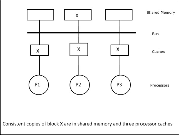
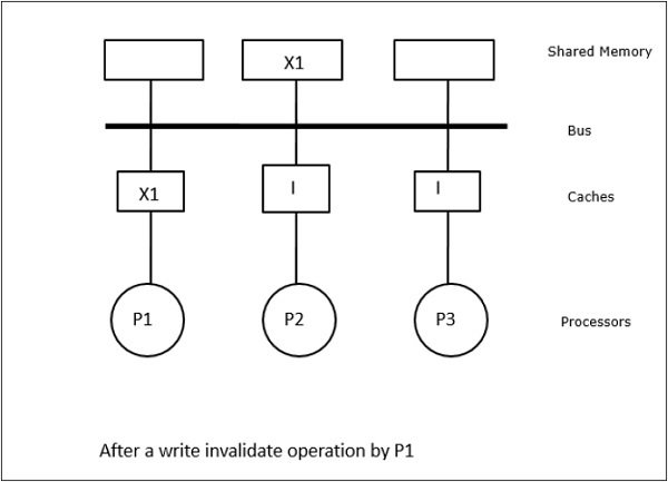
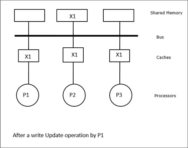
In this case, we have three processors P1, P2, and P3 having a consistent copy of data element X in their local cache memory and in the shared memory (Figure-a). Processor P1 writes X1 in its cache memory using write-invalidate protocol. So, all other copies are invalidated via the bus. It is denoted by I (Figure-b). Invalidated blocks are also known as dirty, i.e. they should not be used. The write-update protocol updates all the cache copies via the bus. By using write back cache, the memory copy is also updated (Figure-c).
Cache Events and Actions
Following events and actions occur on the execution of memory-access and invalidation commands −
Read-miss − When a processor wants to read a block and it is not in the cache, a read-miss occurs. This initiates a bus-read operation. If no dirty copy exists, then the main memory that has a consistent copy, supplies a copy to the requesting cache memory. If a dirty copy exists in a remote cache memory, that cache will restrain the main memory and send a copy to the requesting cache memory. In both the cases, the cache copy will enter the valid state after a read miss.
Write-hit − If the copy is in dirty or reserved state, write is done locally and the new state is dirty. If the new state is valid, write-invalidate command is broadcasted to all the caches, invalidating their copies. When the shared memory is written through, the resulting state is reserved after this first write.
Write-miss − If a processor fails to write in the local cache memory, the copy must come either from the main memory or from a remote cache memory with a dirty block. This is done by sending a read-invalidate command, which will invalidate all cache copies. Then the local copy is updated with dirty state.
Read-hit − Read-hit is always performed in local cache memory without causing a transition of state or using the snoopy bus for invalidation.
Block replacement − When a copy is dirty, it is to be written back to the main memory by block replacement method. However, when the copy is either in valid or reserved or invalid state, no replacement will take place.
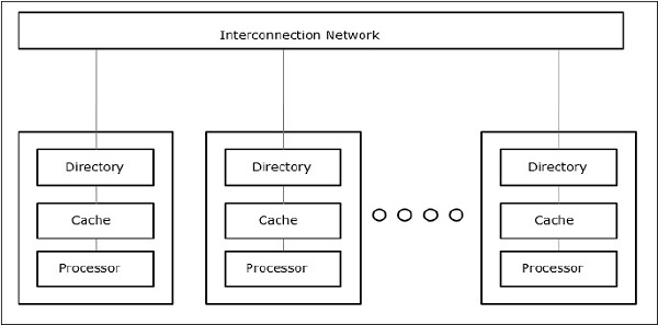
Directory-Based Protocols
By using a multistage network for building a large multiprocessor with hundreds of processors, the snoopy cache protocols need to be modified to suit the network capabilities. Broadcasting being very expensive to perform in a multistage network, the consistency commands is sent only to those caches that keep a copy of the block. This is the reason for development of directory-based protocols for network-connected multiprocessors.
In a directory-based protocols system, data to be shared are placed in a common directory that maintains the coherence among the caches. Here, the directory acts as a filter where the processors ask permission to load an entry from the primary memory to its cache memory. If an entry is changed the directory either updates it or invalidates the other caches with that entry.
Hardware Synchronization Mechanisms
Synchronization is a special form of communication where instead of data control, information is exchanged between communicating processes residing in the same or different processors.
Multiprocessor systems use hardware mechanisms to implement low-level synchronization operations. Most multiprocessors have hardware mechanisms to impose atomic operations such as memory read, write or read-modify-write operations to implement some synchronization primitives. Other than atomic memory operations, some inter-processor interrupts are also used for synchronization purposes.
Cache Coherency in Shared Memory Machines
Maintaining cache coherency is a problem in multiprocessor system when the processors contain local cache memory. Data inconsistency between different caches easily occurs in this system.
The major concern areas are −
- Sharing of writable data
- Process migration
- I/O activity
Sharing of writable data
When two processors (P1 and P2) have same data element (X) in their local caches and one process (P1) writes to the data element (X), as the caches are write-through local cache of P1, the main memory is also updated. Now when P2 tries to read data element (X), it does not find X because the data element in the cache of P2 has become outdated.
Process migration
In the first stage, cache of P1 has data element X, whereas P2 does not have anything. A process on P2 first writes on X and then migrates to P1. Now, the process starts reading data element X, but as the processor P1 has outdated data the process cannot read it. So, a process on P1 writes to the data element X and then migrates to P2. After migration, a process on P2 starts reading the data element X but it finds an outdated version of X in the main memory.
I/O activity
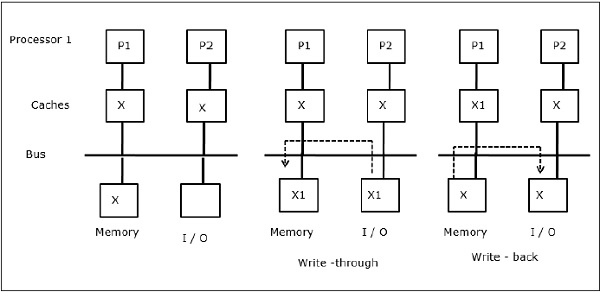
As illustrated in the figure, an I/O device is added to the bus in a two-processor multiprocessor architecture. In the beginning, both the caches contain the data element X. When the I/O device receives a new element X, it stores the new element directly in the main memory. Now, when either P1 or P2 (assume P1) tries to read element X it gets an outdated copy. So, P1 writes to element X. Now, if I/O device tries to transmit X it gets an outdated copy.
Uniform Memory Access (UMA)
Uniform Memory Access (UMA) architecture means the shared memory is the same for all processors in the system. Popular classes of UMA machines, which are commonly used for (file-) servers, are the so-called Symmetric Multiprocessors (SMPs). In an SMP, all system resources like memory, disks, other I/O devices, etc. are accessible by the processors in a uniform manner.
Non-Uniform Memory Access (NUMA)
In NUMA architecture, there are multiple SMP clusters having an internal indirect/shared network, which are connected in scalable message-passing network. So, NUMA architecture is logically shared physically distributed memory architecture.
In a NUMA machine, the cache-controller of a processor determines whether a memory reference is local to the SMPs memory or it is remote. To reduce the number of remote memory accesses, NUMA architectures usually apply caching processors that can cache the remote data. But when caches are involved, cache coherency needs to be maintained. So these systems are also known as CC-NUMA (Cache Coherent NUMA).
Cache Only Memory Architecture (COMA)
COMA machines are similar to NUMA machines, with the only difference that the main memories of COMA machines act as direct-mapped or set-associative caches. The data blocks are hashed to a location in the DRAM cache according to their addresses. Data that is fetched remotely is actually stored in the local main memory. Moreover, data blocks do not have a fixed home location, they can freely move throughout the system.
COMA architectures mostly have a hierarchical message-passing network. A switch in such a tree contains a directory with data elements as its sub-tree. Since data has no home location, it must be explicitly searched for. This means that a remote access requires a traversal along the switches in the tree to search their directories for the required data. So, if a switch in the network receives multiple requests from its subtree for the same data, it combines them into a single request which is sent to the parent of the switch. When the requested data returns, the switch sends multiple copies of it down its subtree.
COMA versus CC-NUMA
Following are the differences between COMA and CC-NUMA.
COMA tends to be more flexible than CC-NUMA because COMA transparently supports the migration and replication of data without the need of the OS.
COMA machines are expensive and complex to build because they need non-standard memory management hardware and the coherency protocol is harder to implement.
Remote accesses in COMA are often slower than those in CC-NUMA since the tree network needs to be traversed to find the data.
Hardware Software Tradeoffs
There are many methods to reduce hardware cost. One method is to integrate the communication assist and network less tightly into the processing node and increasing communication latency and occupancy.
Another method is to provide automatic replication and coherence in software rather than hardware. The latter method provides replication and coherence in the main memory, and can execute at a variety of granularities. It allows the use of off-the-shelf commodity parts for the nodes and interconnect, minimizing hardware cost. This puts pressure on the programmer to achieve good performance.
Relaxed Memory Consistency Models
The memory consistency model for a shared address space defines the constraints in the order in which the memory operations in the same or different locations seem to be executing with respect to one another. Actually, any system layer that supports a shared address space naming model must have a memory consistency model which includes the programmers interface, user-system interface, and the hardware-software interface. Software that interacts with that layer must be aware of its own memory consistency model.
System Specifications
The system specification of an architecture specifies the ordering and reordering of the memory operations and how much performance can actually be gained from it.
Following are the few specification models using the relaxations in program order −
Relaxing the Write-to-Read Program Order − This class of models allow the hardware to suppress the latency of write operations that was missed in the first-level cache memory. When the write miss is in the write buffer and not visible to other processors, the processor can complete reads which hit in its cache memory or even a single read that misses in its cache memory.
Relaxing the Write-to-Read and Write-to-Write Program Orders − Allowing writes to bypass previous outstanding writes to various locations lets multiple writes to be merged in the write buffer before updating the main memory. Thus multiple write misses to be overlapped and becomes visible out of order. The motivation is to further minimize the impact of write latency on processor break time, and to raise communication efficiency among the processors by making new data values visible to other processors.
Relaxing All Program Orders − No program orders are assured by default except data and control dependences within a process. Thus, the benefit is that the multiple read requests can be outstanding at the same time, and in program order can be bypassed by later writes, and can themselves complete out of order, allowing us to hide read latency. This type of models are particularly useful for dynamically scheduled processors, which can continue past read misses to other memory references. They allow many of the re-orderings, even elimination of accesses that are done by compiler optimizations.
The Programming Interface
The programming interfaces assume that program orders do not have to be maintained at all among synchronization operations. It is ensured that all synchronization operations are explicitly labeled or identified as such. Runtime library or the compiler translates these synchronization operations into the suitable order-preserving operations called for by the system specification.
The system then assures sequentially consistent executions even though it may reorder operations among the synchronization operations in any way it desires without disrupting dependences to a location within a process. This allows the compiler sufficient flexibility among synchronization points for the reorderings it desires, and also grants the processor to perform as many reorderings as allowed by its memory model. At the programmers interface, the consistency model should be at least as weak as that of the hardware interface, but need not be the same.
Translation Mechanisms
In most microprocessors, translating labels to order maintaining mechanisms amounts to inserting a suitable memory barrier instruction before and/or after each operation labeled as a synchronization. It would save instructions with individual loads/stores indicating what orderings to enforce and avoiding extra instructions. However, since the operations are usually infrequent, this is not the way that most microprocessors have taken so far.
Overcoming Capacity Limitations
We have dicussed the systems which provide automatic replication and coherence in hardware only in the processor cache memory. A processor cache, without it being replicated in the local main memory first, replicates remotely allocated data directly upon reference.
A problem with these systems is that the scope for local replication is limited to the hardware cache. If a block is replaced from the cache memory, it has to be fetched from remote memory when it is needed again. The main purpose of the systems discussed in this section is to solve the replication capacity problem but still providing coherence in hardware and at fine granularity of cache blocks for efficiency.
Tertiary Caches
To solve the replication capacity problem, one method is to use a large but slower remote access cache. This is needed for functionality, when the nodes of the machine are themselves small-scale multiprocessors and can simply be made larger for performance. It will also hold replicated remote blocks that have been replaced from local processor cache memory.
Cache-only Memory Architectures (COMA)
In COMA machines, every memory block in the entire main memory has a hardware tag linked with it. There is no fixed node where there is always assurance to be space allocated for a memory block. Data dynamically migrates to or is replicated in the main memories of the nodes that access/attract them. When a remote block is accessed, it is replicated in attraction memory and brought into the cache, and is kept consistent in both the places by the hardware. A data block may reside in any attraction memory and may move easily from one to the other.
Reducing Hardware Cost
Reducing cost means moving some functionality of specialized hardware to software running on the existing hardware. It is much easier for software to manage replication and coherence in the main memory than in the hardware cache. The low-cost methods tend to provide replication and coherence in the main memory. For coherence to be controlled efficiently, each of the other functional components of the assist can be benefited from hardware specialization and integration.
Research efforts aim to lower the cost with different approaches, like by performing access control in specialized hardware, but assigning other activities to software and commodity hardware. Another approach is by performing access control in software, and is designed to allot a coherent shared address space abstraction on commodity nodes and networks with no specialized hardware support.
Implications for Parallel Software
Relaxed memory consistency model needs that parallel programs label the desired conflicting accesses as synchronization points. A programming language provides support to label some variables as synchronization, which will then be translated by the compiler to the suitable order-preserving instruction. To restrict compilers own reordering of accesses to shared memory, the compiler can use labels by itself.
Interconnection Network Design
An interconnection network in a parallel machine transfers information from any source node to any desired destination node. This task should be completed with as small latency as possible. It should allow a large number of such transfers to take place concurrently. Moreover, it should be inexpensive as compared to the cost of the rest of the machine.
The network is composed of links and switches, which helps to send the information from the source node to the destination node. A network is specified by its topology, routing algorithm, switching strategy, and flow control mechanism.
Organizational Structure
Interconnection networks are composed of following three basic components −
Links − A link is a cable of one or more optical fibers or electrical wires with a connector at each end attached to a switch or network interface port. Through this, an analog signal is transmitted from one end, received at the other to obtain the original digital information stream.
Switches − A switch is composed of a set of input and output ports, an internal cross-bar connecting all input to all output, internal buffering, and control logic to effect the input-output connection at each point in time. Generally, the number of input ports is equal to the number of output ports.
Network Interfaces − The network interface behaves quite differently than switch nodes and may be connected via special links. The network interface formats the packets and constructs the routing and control information. It may have input and output buffering, compared to a switch. It may perform end-to-end error checking and flow control. Hence, its cost is influenced by its processing complexity, storage capacity, and number of ports.
Interconnection Network
Interconnection networks are composed of switching elements. Topology is the pattern to connect the individual switches to other elements, like processors, memories and other switches. A network allows exchange of data between processors in the parallel system.
Direct connection networks − Direct networks have point-to-point connections between neighboring nodes. These networks are static, which means that the point-to-point connections are fixed. Some examples of direct networks are rings, meshes and cubes.
Indirect connection networks − Indirect networks have no fixed neighbors. The communication topology can be changed dynamically based on the application demands. Indirect networks can be subdivided into three parts: bus networks, multistage networks and crossbar switches.
Bus networks − A bus network is composed of a number of bit lines onto which a number of resources are attached. When busses use the same physical lines for data and addresses, the data and the address lines are time multiplexed. When there are multiple bus-masters attached to the bus, an arbiter is required.
Multistage networks − A multistage network consists of multiple stages of switches. It is composed of axb switches which are connected using a particular interstage connection pattern (ISC). Small 2x2 switch elements are a common choice for many multistage networks. The number of stages determine the delay of the network. By choosing different interstage connection patterns, various types of multistage network can be created.
Crossbar switches − A crossbar switch contains a matrix of simple switch elements that can switch on and off to create or break a connection. Turning on a switch element in the matrix, a connection between a processor and a memory can be made. Crossbar switches are non-blocking, that is all communication permutations can be performed without blocking.
Evaluating Design Trade-offs in Network Topology
If the main concern is the routing distance, then the dimension has to be maximized and a hypercube made. In store-and-forward routing, assuming that the degree of the switch and the number of links were not a significant cost factor, and the numbers of links or the switch degree are the main costs, the dimension has to be minimized and a mesh built.
In worst case traffic pattern for each network, it is preferred to have high dimensional networks where all the paths are short. In patterns where each node is communicating with only one or two nearby neighbors, it is preferred to have low dimensional networks, since only a few of the dimensions are actually used.
Routing
The routing algorithm of a network determines which of the possible paths from source to destination is used as routes and how the route followed by each particular packet is determined. Dimension order routing limits the set of legal paths so that there is exactly one route from each source to each destination. The one obtained by first traveling the correct distance in the high-order dimension, then the next dimension and so on.
Routing Mechanisms
Arithmetic, source-based port select, and table look-up are three mechanisms that high-speed switches use to determine the output channel from information in the packet header. All of these mechanisms are simpler than the kind of general routing computations implemented in traditional LAN and WAN routers. In parallel computer networks, the switch needs to make the routing decision for all its inputs in every cycle, so the mechanism needs to be simple and fast.
Deterministic Routing
A routing algorithm is deterministic if the route taken by a message is determined exclusively by its source and destination, and not by other traffic in the network. If a routing algorithm only selects shortest paths toward the destination, it is minimal, otherwise it is non-minimal.
Deadlock Freedom
Deadlock can occur in a various situations. When two nodes attempt to send data to each other and each begins sending before either receives, a head-on deadlock may occur. Another case of deadlock occurs, when there are multiple messages competing for resources within the network.
The basic technique for proving a network is deadlock free, is to clear the dependencies that can occur between channels as a result of messages moving through the networks and to show that there are no cycles in the overall channel dependency graph; hence there is no traffic patterns that can lead to a deadlock. The common way of doing this is to number the channel resources such that all routes follow a particular increasing or decreasing sequences, so that no dependency cycles arise.
Switch Design
Design of a network depends on the design of the switch and how the switches are wired together. The degree of the switch, its internal routing mechanisms, and its internal buffering decides what topologies can be supported and what routing algorithms can be implemented. Like any other hardware component of a computer system, a network switch contains data path, control, and storage.
Ports
The total number of pins is actually the total number of input and output ports times the channel width. As the perimeter of the chip grows slowly compared to the area, switches tend to be pin limited.
Internal Datapath
The datapath is the connectivity between each of the set of input ports and every output port. It is generally referred to as the internal cross-bar. A non-blocking cross-bar is one where each input port can be connected to a distinct output in any permutation simultaneously.
Channel Buffers
The organization of the buffer storage within the switch has an important impact on the switch performance. Traditional routers and switches tend to have large SRAM or DRAM buffers external to the switch fabric, while in VLSI switches the buffering is internal to the switch and comes out of the same silicon budget as the datapath and the control section. As the chip size and density increases, more buffering is available and the network designer has more options, but still the buffer real-estate comes at a prime choice and its organization is important.
Flow Control
When multiple data flows in the network attempt to use the same shared network resources at the same time, some action must be taken to control these flows. If we dont want to lose any data, some of the flows must be blocked while others proceed.
The problem of flow control arises in all networks and at many levels. But it is qualitatively different in parallel computer networks than in local and wide area networks. In parallel computers, the network traffic needs to be delivered about as accurately as traffic across a bus and there are a very large number of parallel flows on very small-time scale.
Latency Tolerance
The speed of microprocessors has increased by more than a factor of ten per decade, but the speed of commodity memories (DRAMs) has only doubled, i.e., access time is halved. Therefore, the latency of memory access in terms of processor clock cycles grow by a factor of six in 10 years. Multiprocessors intensified the problem.
In bus-based systems, the establishment of a high-bandwidth bus between the processor and the memory tends to increase the latency of obtaining the data from the memory. When the memory is physically distributed, the latency of the network and the network interface is added to that of the accessing the local memory on the node.
Latency usually grows with the size of the machine, as more nodes imply more communication relative to computation, more jump in the network for general communication, and likely more contention. The main goal of hardware design is to reduce the latency of the data access while maintaining high, scalable bandwidth.
Overview of Latency Tolerance
How latency tolerance is handled is best understood by looking at the resources in the machine and how they are utilized. From the processor point of view, the communication architecture from one node to another can be viewed as a pipeline. The stages of the pipeline include network interfaces at the source and destination, as well as in the network links and switches along the way. There are also stages in the communication assist, the local memory/cache system, and the main processor, depending on how the architecture manages communication.
The utilization problem in the baseline communication structure is either the processor or the communication architecture is busy at a given time, and in the communication pipeline only one stage is busy at a time as the single word being transmitted makes its way from source to destination. The aim in latency tolerance is to overlap the use of these resources as much as possible.
Latency Tolerance in Explicit Message Passing
The actual transfer of data in message-passing is typically sender-initiated, using a send operation. A receive operation does not in itself motivate data to be communicated, but rather copies data from an incoming buffer into the application address space. Receiver-initiated communication is done by issuing a request message to the process that is the source of the data. The process then sends the data back via another send.
A synchronous send operation has communication latency equal to the time it takes to communicate all the data in the message to the destination, and the time for receive processing, and the time for an acknowledgment to be returned. The latency of a synchronous receive operation is its processing overhead; which includes copying the data into the application, and the additional latency if the data has not yet arrived. We would like to hide these latencies, including overheads if possible, at both ends.
Latency Tolerance in a Shared Address Space
The baseline communication is through reads and writes in a shared address space. For convenience, it is called read-write communication. Receiver-initiated communication is done with read operations that result in data from another processors memory or cache being accessed. If there is no caching of shared data, sender-initiated communication may be done through writes to data that are allocated in remote memories.
With cache coherence, the effect of writes is more complex: either writes leads to sender or receiver-initiated communication depends on the cache coherence protocol. Either receiver-initiated or sender-initiated, the communication in a hardware-supported read writes shared address space is naturally fine-grained, which makes tolerance latency very important.
Block Data Transfer in a Shared Address Space
In a shared address space, either by hardware or software the coalescing of data and the initiation of block transfers can be done explicitly in the user program or transparently by the system. Explicit block transfers are initiated by executing a command similar to a send in the user program. The send command is explained by the communication assist, which transfers the data in a pipelined manner from the source node to the destination. At the destination, the communication assist pulls the data words in from the network interface and stores them in the specified locations.
There are two prime differences from send-receive message passing, both of which arise from the fact that the sending process can directly specify the program data structures where the data is to be placed at the destination, since these locations are in the shared address space.
Proceeding Past Long-latency Events in a Shared Address Space
If the memory operation is made non-blocking, a processor can proceed past a memory operation to other instructions. For writes, this is usually quite simple to implement if the write is put in a write buffer, and the processor goes on while the buffer takes care of issuing the write to the memory system and tracking its completion as required. The difference is that unlike a write, a read is generally followed very soon by an instruction that needs the value returned by the read.
Pre-communication in a Shared Address Space
Pre-communication is a technique that has already been widely adopted in commercial microprocessors, and its importance is likely to increase in the future. A prefetch instruction does not replace the actual read of the data item, and the prefetch instruction itself must be non-blocking, if it is to achieve its goal of hiding latency through overlap.
In this case, as shared data is not cached, the prefetched data is brought into a special hardware structure called a prefetch buffer. When the word is actually read into a register in the next iteration, it is read from the head of the prefetch buffer rather than from memory. If the latency to hide were much bigger than the time to compute single loop iteration, we would prefetch several iterations ahead and there would potentially be several words in the prefetch buffer at a time.
Multithreading in a Shared Address Space
In terms of hiding different types of latency, hardware-supported multithreading is perhaps the versatile technique. It has the following conceptual advantages over other approaches −
It requires no special software analysis or support.
As it is invoked dynamically, it can handle unpredictable situations, like cache conflicts, etc. just as well as predictable ones.
Like prefetching, it does not change the memory consistency model since it does not reorder accesses within a thread.
While the previous techniques are targeted at hiding memory access latency, multithreading can potentially hide the latency of any long-latency event just as easily, as long as the event can be detected at runtime. This includes synchronization and instruction latency as well.
This trend may change in future, as latencies are becoming increasingly longer as compared to processor speeds. Also with more sophisticated microprocessors that already provide methods that can be extended for multithreading, and with new multithreading techniques being developed to combine multithreading with instruction-level parallelism, this trend certainly seems to be undergoing some change in future.
