- Home
- Introduction
- Convergence of Parallel Architectures
- Parallel Computer Models
- Processor in Parallel Systems
- Multiprocessors and Multicomputers
- Cache Coherence & Synchronization
- Hardware-Software Tradeoffs
- Interconnection Network Design
- Latency Tolerance
Multiprocessors and Multicomputers
We will discuss multiprocessors and multicomputers in this chapter.
Multiprocessor System Interconnects
Parallel processing needs the use of efficient system interconnects for fast communication among the Input/Output and peripheral devices, multiprocessors and shared memory.
Hierarchical Bus Systems
A hierarchical bus system consists of a hierarchy of buses connecting various systems and sub-systems/components in a computer. Each bus is made up of a number of signal, control, and power lines. Different buses like local buses, backplane buses and I/O buses are used to perform different interconnection functions.
Local buses are the buses implemented on the printed-circuit boards. A backplane bus is a printed circuit on which many connectors are used to plug in functional boards. Buses which connect input/output devices to a computer system are known as I/O buses.
Crossbar switch and Multiport Memory
Switched networks give dynamic interconnections among the inputs and outputs. Small or medium size systems mostly use crossbar networks. Multistage networks can be expanded to the larger systems, if the increased latency problem can be solved.
Both crossbar switch and multiport memory organization is a single-stage network. Though a single stage network is cheaper to build, but multiple passes may be needed to establish certain connections. A multistage network has more than one stage of switch boxes. These networks should be able to connect any input to any output.
Multistage and Combining Networks
Multistage networks or multistage interconnection networks are a class of high-speed computer networks which is mainly composed of processing elements on one end of the network and memory elements on the other end, connected by switching elements.
These networks are applied to build larger multiprocessor systems. This includes Omega Network, Butterfly Network and many more.
Multicomputers
Multicomputers are distributed memory MIMD architectures. The following diagram shows a conceptual model of a multicomputer −
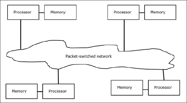
Multicomputers are message-passing machines which apply packet switching method to exchange data. Here, each processor has a private memory, but no global address space as a processor can access only its own local memory. So, communication is not transparent: here programmers have to explicitly put communication primitives in their code.
Having no globally accessible memory is a drawback of multicomputers. This can be solved by using the following two schemes −
- Virtual Shared Memory (VSM)
- Shared Virtual Memory (SVM)
In these schemes, the application programmer assumes a big shared memory which is globally addressable. If required, the memory references made by applications are translated into the message-passing paradigm.
Virtual Shared Memory (VSM)
VSM is a hardware implementation. So, the virtual memory system of the Operating System is transparently implemented on top of VSM. So, the operating system thinks it is running on a machine with a shared memory.
Shared Virtual Memory (SVM)
SVM is a software implementation at the Operating System level with hardware support from the Memory Management Unit (MMU) of the processor. Here, the unit of sharing is Operating System memory pages.
If a processor addresses a particular memory location, the MMU determines whether the memory page associated with the memory access is in the local memory or not. If the page is not in the memory, in a normal computer system it is swapped in from the disk by the Operating System. But, in SVM, the Operating System fetches the page from the remote node which owns that particular page.
Three Generations of Multicomputers
In this section, we will discuss three generations of multicomputers.
Design Choices in the Past
While selecting a processor technology, a multicomputer designer chooses low-cost medium grain processors as building blocks. Majority of parallel computers are built with standard off-the-shelf microprocessors. Distributed memory was chosen for multi-computers rather than using shared memory, which would limit the scalability. Each processor has its own local memory unit.
For interconnection scheme, multicomputers have message passing, point-to-point direct networks rather than address switching networks. For control strategy, designer of multi-computers choose the asynchronous MIMD, MPMD, and SMPD operations. Caltechs Cosmic Cube (Seitz, 1983) is the first of the first generation multi-computers.
Present and Future Development
The next generation computers evolved from medium to fine grain multicomputers using a globally shared virtual memory. Second generation multi-computers are still in use at present. But using better processor like i386, i860, etc. second generation computers have developed a lot.
Third generation computers are the next generation computers where VLSI implemented nodes will be used. Each node may have a 14-MIPS processor, 20-Mbytes/s routing channels and 16 Kbytes of RAM integrated on a single chip.
The Intel Paragon System
Previously, homogeneous nodes were used to make hypercube multicomputers, as all the functions were given to the host. So, this limited the I/O bandwidth. Thus to solve large-scale problems efficiently or with high throughput, these computers could not be used.The Intel Paragon System was designed to overcome this difficulty. It turned the multicomputer into an application server with multiuser access in a network environment.
Message Passing Mechanisms
Message passing mechanisms in a multicomputer network needs special hardware and software support. In this section, we will discuss some schemes.
Message-Routing Schemes
In multicomputer with store and forward routing scheme, packets are the smallest unit of information transmission. In wormholerouted networks, packets are further divided into flits. Packet length is determined by the routing scheme and network implementation, whereas the flit length is affected by the network size.
In Store and forward routing, packets are the basic unit of information transmission. In this case, each node uses a packet buffer. A packet is transmitted from a source node to a destination node through a sequence of intermediate nodes. Latency is directly proportional to the distance between the source and the destination.
In wormhole routing, the transmission from the source node to the destination node is done through a sequence of routers. All the flits of the same packet are transmitted in an inseparable sequence in a pipelined fashion. In this case, only the header flit knows where the packet is going.
Deadlock and Virtual Channels
A virtual channel is a logical link between two nodes. It is formed by flit buffer in source node and receiver node, and a physical channel between them. When a physical channel is allocated for a pair, one source buffer is paired with one receiver buffer to form a virtual channel.
When all the channels are occupied by messages and none of the channel in the cycle is freed, a deadlock situation will occur. To avoid this a deadlock avoidance scheme has to be followed.
