
Article Categories
- All Categories
-
 Data Structure
-
 Networking
-
 RDBMS
RDBMS
-
 Operating System
-
 Java
Java
-
 MS Excel
-
 iOS
iOS
-
 HTML
HTML
-
 CSS
CSS
-
 Android
-
 Python
-
 C Programming
-
 C++
C++
-
 C#
C#
-
 MongoDB
-
 MySQL
MySQL
-
 Javascript
-
 PHP
PHP
Opcode Fetch (OF) machine cycle in 8085 Microprocessor
The OF machine cycle are constituted by the four clock cycles shown in the figure below. Here in these four clock cycles we execute opcode fetch, decode, and complete the execution. Moreover, in the instructions of 2- and 3-byte, and also in the instructions of 1 byte like ‘MOV B, M’, only OF and decode operations gets completed in these four cycles of the clock. Hence opcode fetch is consisted by the OF machine cycle and for performing the decode operation, and in some rare cases execution. For performing some typical instructions like DCX B, the six states are provided by the OF machine cycle. So indication of a machine cycle is done, similar to OF, and the total number of T states are needed when no wait states are found. If the wait states are needed it totally depends on the memory speed and the peripheral chips which we have used in the system. In the first three clock cycles IR register receives 4EH from the location of memory C001H.We do the decoding in T4 states. The control unit (CU) gets the opcode which corresponds to the 1-byte instruction whose mnemonic code is MOV C, M. The OF machine cycle is constituted by these 4 T states which we have described previously. In the meantime, we increment the contents of the PC to C002H. But we will not release C002H from this point as such the instruction MOV C, M is does not gets executed.
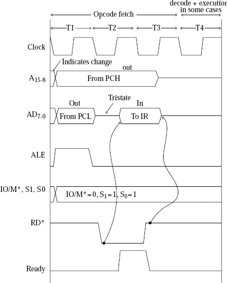
In addition to address information, status signals as shown in the following are activated by the control unit during T1.
ALE is equal to 1, the address bits are indicated which are present on AD7-0;
IO/M* is equal to 0, it indicates the address which are for the memory;
If S1 is equal 1 and S0 is equal to 0 then it indicates that it is MR machine cycle.
As an example, let us consider the instruction STC and explain its OF.
In 8085 Instruction set, STC stands for “SeT the Carry flag”. It sets the cy flag to the 1 state, immaterial of its earlier value. It performs set operation on the cy flag, and the result is stored back in the cy flag.
|
Mnemonics, Operand |
Opcode (in HEX) |
Bytes |
|---|---|---|
| STC |
37 |
1 |
The result of execution of this instruction has been depicted in the following tracing table –
| |
Before |
After |
|---|---|---|
|
(Cy) |
1 |
1 |
The result of execution of this instruction has been depicted in the following tracing table –
| |
Before |
After |
|
|---|---|---|---|
|
(Cy) |
0 |
1 |
The result of execution of this instruction has been depicted in the following tracing table –
|
Address |
Hex Codes |
Mnemonic |
Comment |
|---|---|---|---|
| 2000 |
37 |
STC |
Set the Cy flag i.e. set Cy=1 |
The timing diagram against this instruction STC execution is as follows –
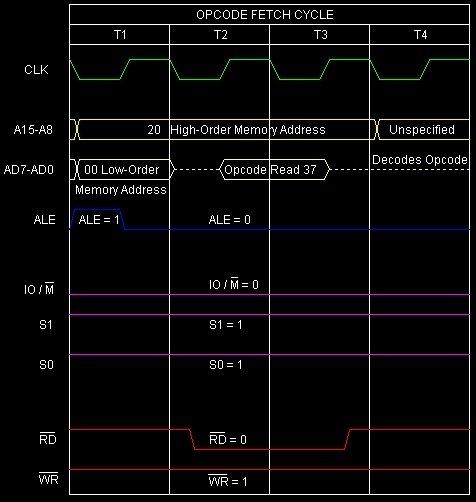
Summary: So this instruction STC requires 1-Byte, 1-Machine Cycle (Opcode Fetch) and 4 T-States for execution as shown in the timing diagram.

13K+ Views
