
Article Categories
- All Categories
-
 Data Structure
-
 Networking
-
 RDBMS
RDBMS
-
 Operating System
-
 Java
Java
-
 MS Excel
-
 iOS
iOS
-
 HTML
HTML
-
 CSS
CSS
-
 Android
-
 Python
-
 C Programming
-
 C++
C++
-
 C#
C#
-
 MongoDB
-
 MySQL
MySQL
-
 Javascript
-
 PHP
PHP
-
 Economics & Finance
Frame Structure for OFDMA with Time Division Duplexing
Orthogonal frequency division multiple access (OFDMA) is a multi-user version of digital data modulation scheme OFDM (orthogonal frequency division multiplexing). In OFDM, a single stream of data is divided into several separate sub-streams for transmission via multiple channels. OFDM uses the principle of frequency division multiplexing (FDM), where the available bandwidth is divided into a set of sub-streams having separate frequency bands.
In OFDMA, multiple access is achieved by assignment of different subsets of subcarriers to individual stations. This permits transmission to go on simultaneously at lower data rate from several stations.
The stations assigned to a given subcarrier alternate between sending and receiving using time division duplexing (TDD). In TDD, the uplink of a station is separated from the downlink by allocating different time slots in the same frequency band of a subcarrier. This allows asymmetric flow of data for upstream and downstream. Each station is allotted separate time slots for uplink and downlink transmission.
Frame Structure of OFDMA with TDD
The following diagram shows the frame structure that needs to be used for orthogonal frequency division multiple access with time division duplexing −
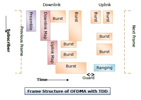
The particulars of the frame that is sent with respect to time is as follows −
- Each frame starts with a preamble. The function of the preamble is to synchronize all the stations that are contending for the wireless channel.
- The preamble is followed by two maps for downlink and uplink bursts. They hold information about how the downlink bursts and the uplink bursts are assigned over the frame in the subcarrier.
- The above maps are controlled by the base station. This adds flexibility to the system, as the base station can allot different amount of bandwidth to the stations for each frame as per the requirements of the stations.
- After the maps are transmitted, the base station sends bursts of downlink data streams to the concerned stations according to the timings laid down in the downlink map.
- Downlink traffic ends with a guard band that allows the stations to switch from receiving to transmitting mode.
- The stations then send their data in bursts of uplink data streams to the base station.
- Among the uplink bursts, one is reserved for ranging. In the ranging process, new stations can send their upstream data. The stations request for bandwidth to connect to the base station and adjust their burst time according to the ranging slot.
- After the whole frame has been sent, an inter-frame spacing is kept and then the base station initiates transmission of the next frame.

838 Views
