
Article Categories
- All Categories
-
 Data Structure
-
 Networking
-
 RDBMS
RDBMS
-
 Operating System
-
 Java
Java
-
 MS Excel
-
 iOS
iOS
-
 HTML
HTML
-
 CSS
CSS
-
 Android
-
 Python
-
 C Programming
-
 C++
C++
-
 C#
C#
-
 MongoDB
-
 MySQL
MySQL
-
 Javascript
-
 PHP
PHP
-
 Economics & Finance
Evaluation of Boolean expression
We write a program in 8085 in the assembly language just for the evaluation of only wo Boolean expressions of 4 variables by using the interface of logic controller. The output of the program should be logically tested automatically by the output by the input changing from the inputs from 0000, 0001, … to 1111 just to press any key.
![]()
Let us say we want to evaluate the following Boolean expressions.
First of all, truth table for the Boolean expressions is written down as shown in the following table.
|
P |
Q |
R |
S |
X |
Y |
|---|---|---|---|---|---|
| 0 |
0 |
0 |
0 |
1 |
0 |
| 0 |
0 |
0 |
1 |
0 |
0 |
| 0 |
0 |
1 |
0 |
1 |
0 |
| 0 |
0 |
1 |
1 |
0 |
0 |
| 0 |
1 |
0 |
0 |
1 |
0 |
| 0 |
1 |
0 |
1 |
0 |
0 |
| 0 |
1 |
1 |
0 |
1 |
0 |
| 0 |
1 |
1 |
1 |
0 |
0 |
| 1 |
0 |
0 |
0 |
0 |
1 |
| 1 |
0 |
0 |
1 |
0 |
1 |
| 1 |
0 |
1 |
0 |
1 |
0 |
| 1 |
0 |
1 |
1 |
0 |
0 |
| 1 |
1 |
0 |
0 |
0 |
0 |
| 1 |
1 |
0 |
1 |
1 |
1 |
| 1 |
1 |
1 |
0 |
0 |
0 |
| 1 |
1 |
1 |
1 |
0 |
0 |
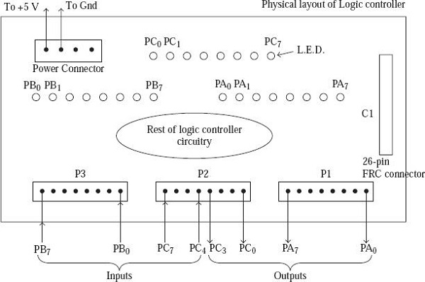
The inputs of the PQRS gets connected to PB3, PB2, PB1, and PB0 of 8255 respectively. The output terminal of X and Y outputs gets connected to the PA1 and PA0, respectively. The Program Port C should be lower just for the output and to be connected to PC3-0 of the lines of the input PB3-0. We just increment the value in the Port C by just lowering by lower by 1just whenever we press a key. This results in the increment of the port B, rather for the depression of every key. The interface of the logic controller just provides a buffer of 12 output lines and also a buffer of 12 input lines to the user. The output lines 12 just gets connected to the lower Ports of A and C (lower) of 8255 on the ALS kit. The output status of each of these lines of output of 8255 gets displayed by using the light emitting diodes called as (LED). In the Fig below, the connections get connected for the making of only one of the made to only one of the output lines of 8255 as shown below.
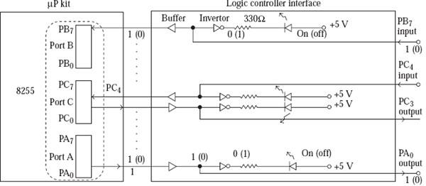
Values within parenthesis correspond to each other. Similarly, those outside parentheses correspond to each other. For example, if PB7 input is a1, the buffer output will also be a1, the inverter output will be 0, and the LED will be On.
The truth table is stored in memory as a look up table, say from location C100H. The following values (corresponding to X and Y in the LS bit positions) are stored in consecutive locations starting from C100H.
02, 00, 02, 00, 02, 00, 02, 00, 01, 01, 02, 00, 00, 03, 00, 00
Program
; FILE NAME BOOLEAN.ASM
ORG C100H
TABLE DB 02H, 00H, 02H, 00H, 02H, 00H, 02H, 00H
DB 01H, 01H, 02H, 00H, 00H, 03H, 00H, 00H

ORG C000H

PA EQU D8H
PB EQU D9H
PC EQU DAH
CTRL EQU DBH

MVI A, 10001010B
OUT CTRL ; Configure 8255 ports

LOOP: IN PB
ANI 0FH ; Now A will contain PQRS input value

LXI H, TABLE
ADD L
MOV L, A ; Point HL to proper row in the truth table

MOV A, M
OUT PA ; Output XY from truth table to display
JMP LOOP

582 Views
