- Electrical Machines - Home
- Basic Concepts
- Electromechanical Energy Conversion
- Energy Stored in Magnetic Field
- Singly-Excited and Doubly Excited Systems
- Rotating Electrical Machines
- Electrical Machines Types
- Faraday’s Laws of Electromagnetic Induction
- Concept of Induced EMF
- Fleming's Left Hand and Right Hand Rules
- Transformers
- Electrical Transformer
- Construction of Transformer
- EMF Equation of Transformer
- Turns Ratio and Voltage Transformation Ratio
- Ideal Transformer
- Practical Transformer
- Ideal and Practical Transformers
- Transformer on DC
- Losses in a Transformer
- Efficiency of Transformer
- 3-Phase Transformer
- Types of Transformers
- More on Transformers
- Transformer Working Principle
- Single-Phase Transformer Working Principle
- 3-Phase Transformer Principle
- 3-Phase Induction Motor Torque-Slip
- 3-Phase Induction Motor Torque-Speed
- 3-Phase Transformer Harmonics
- Double-Star Connection (3-6 Phase)
- Double-delta Connection (3-6 Phase)
- Transformer Ratios
- Voltage Regulation
- Delta-Star Connection (3-Phase)
- Star-Delta Connection (3-Phase)
- Autotransformer Conversion
- Back-to-back Test (Sumpner's Test)
- Transformer Voltage Drop
- Autotransformer Output
- Open and Short Circuit Test
- 3-Phase Autotransformer
- Star-Star Connection
- 6-Phase Diametrical Connections
- Circuit Test (Three-Winding)
- Potential Transformer
- Transformers Parallel Operation
- Open Delta (V-V) Connection
- Autotransformer
- Current Transformer
- No-Load Current Wave
- Transformer Inrush Current
- Transformer Vector Groups
- 3 to 12-Phase Transformers
- Scott-T Transformer Connection
- Transformer kVA Rating
- Three-Winding Transformer
- Delta-Delta Connection Transformer
- Transformer DC Supply Issue
- Equivalent Circuit Transformer
- Simplified Equivalent Circuit of Transformer
- Transformer No-Load Condition
- Transformer Load Condition
- OTI WTI Transformer
- CVT Transformer
- Isolation vs Regular Transformer
- Dry vs Oil-Filled
- DC Machines
- Construction of DC Machines
- Types of DC Machines
- Working Principle of DC Generator
- EMF Equation of DC Generator
- Derivation of EMF Equation DC Generator
- Types of DC Generators
- Working Principle of DC Motor
- Back EMF in DC Motor
- Types of DC Motors
- Losses in DC Machines
- Applications of DC Machines
- More on DC Machines
- DC Generator
- DC Generator Armature Reaction
- DC Generator Commutator Action
- Stepper vs DC Motors
- DC Shunt Generators Critical Resistance
- DC Machines Commutation
- DC Motor Characteristics
- Synchronous Generator Working Principle
- DC Generator Characteristics
- DC Generator Demagnetizing & Cross-Magnetizing
- DC Motor Voltage & Power Equations
- DC Generator Efficiency
- Electric Breaking of DC Motors
- DC Motor Efficiency
- Four Quadrant Operation of DC Motors
- Open Circuit Characteristics of DC Generators
- Voltage Build-Up in Self-Excited DC Generators
- Types of Armature Winding in DC Machines
- Torque in DC Motors
- Swinburne’s Test of DC Machine
- Speed Control of DC Shunt Motor
- Speed Control of DC Series Motor
- DC Motor of Speed Regulation
- Hopkinson's Test
- Permanent Magnet DC Motor
- Permanent Magnet Stepper Motor
- DC Servo Motor Theory
- DC Series vs Shunt Motor
- BLDC Motor vs PMSM Motor
- Induction Motors
- Introduction to Induction Motor
- Single-Phase Induction Motor
- 3-Phase Induction Motor
- Construction of 3-Phase Induction Motor
- 3-Phase Induction Motor on Load
- Characteristics of 3-Phase Induction Motor
- Speed Regulation and Speed Control
- Methods of Starting 3-Phase Induction Motors
- More on Induction Motors
- 3-Phase Induction Motor Working Principle
- 3-Phase Induction Motor Rotor Parameters
- Double Cage Induction Motor Equivalent Circuit
- Induction Motor Equivalent Circuit Models
- Slip Ring vs Squirrel Cage Induction Motors
- Single-Cage vs Double-Cage Induction Motor
- Induction Motor Equivalent Circuits
- Induction Motor Crawling & Cogging
- Induction Motor Blocked Rotor Test
- Induction Motor Circle Diagram
- 3-Phase Induction Motors Applications
- 3-Phase Induction Motors Torque Ratios
- Induction Motors Power Flow Diagram & Losses
- Determining Induction Motor Efficiency
- Induction Motor Speed Control by Pole-Amplitude Modulation
- Induction Motor Inverted or Rotor Fed
- High Torque Cage Motors
- Double-Cage Induction Motor Torque-Slip Characteristics
- 3-Phase Induction Motors Starting Torque
- 3-phase Induction Motor - Rotor Resistance Starter
- 3-phase Induction Motor Running Torque
- 3-Phase Induction Motor - Rotating Magnetic Field
- Isolated Induction Generator
- Capacitor-Start Induction Motor
- Capacitor-Start Capacitor-Run Induction Motor
- Winding EMFs in 3-Phase Induction Motors
- Split-Phase Induction Motor
- Shaded Pole Induction Motor
- Repulsion-Start Induction-Run Motor
- Repulsion Induction Motor
- PSC Induction Motor
- Single-Phase Induction Motor Performance Analysis
- Linear Induction Motor
- Single-Phase Induction Motor Testing
- 3-Phase Induction Motor Fault Types
- Synchronous Machines
- Introduction to 3-Phase Synchronous Machines
- Construction of Synchronous Machine
- Working of 3-Phase Alternator
- Armature Reaction in Synchronous Machines
- Output Power of 3-Phase Alternator
- Losses and Efficiency of an Alternator
- Losses and Efficiency of 3-Phase Alternator
- Working of 3-Phase Synchronous Motor
- Equivalent Circuit and Power Factor of Synchronous Motor
- Power Developed by Synchronous Motor
- More on Synchronous Machines
- AC Motor Types
- Induction Generator (Asynchronous Generator)
- Synchronous Speed Slip of 3-Phase Induction Motor
- Armature Reaction in Alternator at Leading Power Factor
- Armature Reaction in Alternator at Lagging Power Factor
- Stationary Armature vs Rotating Field Alternator Advantages
- Synchronous Impedance Method for Voltage Regulation
- Saturated & Unsaturated Synchronous Reactance
- Synchronous Reactance & Impedance
- Significance of Short Circuit Ratio in Alternator
- Hunting Effect Alternator
- Hydrogen Cooling in Synchronous Generators
- Excitation System of Synchronous Machine
- Equivalent Circuit Phasor Diagram of Synchronous Generator
- EMF Equation of Synchronous Generator
- Cooling Methods for Synchronous Generators
- Assumptions in Synchronous Impedance Method
- Armature Reaction at Unity Power Factor
- Voltage Regulation of Alternator
- Synchronous Generator with Infinite Bus Operation
- Zero Power Factor of Synchronous Generator
- Short Circuit Ratio Calculation of Synchronous Machines
- Speed-Frequency Relationship in Alternator
- Pitch Factor in Alternator
- Max Reactive Power in Synchronous Generators
- Power Flow Equations for Synchronous Generator
- Potier Triangle for Voltage Regulation in Alternators
- Parallel Operation of Alternators
- Load Sharing in Parallel Alternators
- Slip Test on Synchronous Machine
- Constant Flux Linkage Theorem
- Blondel's Two Reaction Theory
- Synchronous Machine Oscillations
- Ampere Turn Method for Voltage Regulation
- Salient Pole Synchronous Machine Theory
- Synchronization by Synchroscope
- Synchronization by Synchronizing Lamp Method
- Sudden Short Circuit in 3-Phase Alternator
- Short Circuit Transient in Synchronous Machines
- Power-Angle of Salient Pole Machines
- Prime-Mover Governor Characteristics
- Power Input of Synchronous Generator
- Power Output of Synchronous Generator
- Power Developed by Salient Pole Motor
- Phasor Diagrams of Cylindrical Rotor Moto
- Synchronous Motor Excitation Voltage Determination
- Hunting Synchronous Motor
- Self-Starting Synchronous Motor
- Unidirectional Torque Production in Synchronous Motor
- Effect of Load Change on Synchronous Motor
- Field Excitation Effect on Synchronous Motor
- Output Power of Synchronous Motor
- Input Power of Synchronous Motor
- V Curves & Inverted V Curves of Synchronous Motor
- Torque in Synchronous Motor
- Construction of 3-Phase Synchronous Motor
- Synchronous Motor
- Synchronous Condenser
- Power Flow in Synchronous Motor
- Types of Faults in Alternator
- Miscellaneous Topics
- Electrical Generator
- Determining Electric Motor Load
- Solid State Motor Starters
- Characteristics of Single-Phase Motor
- Types of AC Generators
- Three-Point Starter
- Four-Point Starter
- Ward Leonard Speed Control Method
- Pole Changing Method
- Stator Voltage Control Method
- DOL Starter
- Star-Delta Starter
- Hysteresis Motor
- 2-Phase & 3-Phase AC Servo Motors
- Repulsion Motor
- Reluctance Motor
- Stepper Motor
- PCB Motor
- Single-Stack Variable Reluctance Stepper Motor
- Schrage Motor
- Hybrid Schrage Motor
- Multi-Stack Variable Reluctance Stepper Motor
- Universal Motor
- Step Angle in Stepper Motor
- Stepper Motor Torque-Pulse Rate Characteristics
- Distribution Factor
- Electrical Machines Basic Terms
- Synchronizing Torque Coefficient
- Synchronizing Power Coefficient
- Metadyne
- Motor Soft Starter
- CVT vs PT
- Metering CT vs Protection CT
- Stator and Rotor in Electrical Machines
- Electric Motor Winding
- Electric Motor
- Useful Resources
- Quick Guide
- Resources
- Discussion
Electrical Transformer
In electrical and electronic systems, the electrical transformer is one of the most useful electrical machine. An electrical transformer can increase or decrease the magnitude of alternating voltage or current. It is the major reason behind the widespread use of alternating currents rather than direct current. A transformer does not have any moving part. Therefore, it has very high efficiency up to 99% and very strong and durable construction.
Electrical Transformer
A transformer or electrical transformer is a static AC electrical machine which changes the level of alternating voltage or alternating current without changing in the frequency of the supply.
A typical transformer consists of two windings namely primary winding and secondary winding. These two windings are interlinked by a common magnetic circuit for transferring electrical energy between them.
Principle of Transformer Operation
The operation of the transformer is based on the principle of mutual inductance, which states that when a changing magnetic field of one coil links to another coil, an EMF is induced in the second coil.
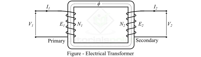
When an alternating voltage V1 is applied to the primary winding, an alternating current flows through it and produces an alternating magnetic flux. This changing magnetic flux flows through the core of the transformer and links to the secondary winding. According to Faradays law of electromagnetic induction, an EMF E2 is induced in the secondary winding due to the linkage of changing magnetic flux of the primary winding. If the secondary winding circuit is closed by connecting a load, then this induced EMF E2 in the secondary winding causes a secondary current I2 to flow through the load.
Although the changing magnetic flux of primary winding is also linked with the primary winding itself. Hence, an EMF E1 is induced in the primary winding due to its own inductance effect. The value of E1 and E2 can be given by the following formulae,
$$\mathrm{\mathit{E_{\mathrm{1}}}\:=\:-\mathit{N_{\mathrm{1}}}\frac{\mathit{d\phi }}{\mathit{dt}}}$$
$$\mathrm{\mathit{E_{\mathrm{2}}}\:=\:-\mathit{N_{\mathrm{2}}}\frac{\mathit{d\phi }}{\mathit{dt}}}$$
Where N1 and N2 are the number of turns in the primary winding and secondary winding respectively.
On taking the ratio of E2 and E1, we get,
$$\mathrm{\frac{\mathit{E_{\mathrm{2}}}}{\mathit{E_{\mathrm{1}}}}\:=\:\frac{\mathit{N_{\mathrm{2}}}}{\mathit{N_{\mathrm{1}}}}}$$
This expression is known as transformation ratio of the transformer. The transformation ratio depends on the number of turns in primary and secondary windings. Which means the magnitude of output voltage depends on the relative number of turns in primary and secondary windings.
If N2 > N1, then E2 > E1, i.e., the output voltage of the transformer is more than the input voltage, and such a transformer is known as set-up transformer. On the other hand, if N1 > N2, then E1 > E2 i.e., the output voltage is less than input voltage, such a transformer is called step-down transformer.
From the circuit diagram of the transformer, we can see that there is no electrical connection between the primary and secondary instead they are linked with the help of a magnetic field. Thus, a transformer enables us to transfer AC electrical power magnetically from one circuit to another which a change in the voltage and current level.
Types of Transformer
Based on operation, a transformer can be of the following three types −
- Step-up Transformer − Increases the voltage level from a lower voltage level.
- Step-down Transformer − Decreases the voltage level from a higher voltage level.
- Isolation Transformer − Does not change the voltage, but separates two electrical circuit electrically. It is also known as 1 to 1 transformer.
EMF Equation of Transformer
The mathematical expression that gives the value of induced EMF in windings of the transformer is known as emf equation of the transformer.
The EMF equation for primary winding is given by,
$$\mathrm{E_{1} \: = \: 4.44f \: \phi _{m}N_{1} \: = \: 4.44f \: B_{m}AN_{1}}$$
The EMF equation for secondary winding is given by,
$$\mathrm{E_{2} \: = \: 4.44f \: \phi _{m}N_{2} \: = \: 4.44f \: B_{m}AN_{2}}$$
Where, f is the supply frequency, m is the maximum flux in the core, Bm is the maximum flux density in the core, A is the area of cross-section of the core, 1 and 2 are the number of turns in the primary and secondary windings.
Turns Ratio of Transformer
The ratio of number of turns in the primary winding to the number of turns in the secondary winding of a transformer is referred to as turns ratio of the transformer. It is usually denoted by the symbol a.
$$\mathrm{Turns \: Ratio, a \: = \: \frac{Primary \: winding \: turns \: (N_{1})}{Secondary \: winding \: turns \: (N_{2})}}$$
Voltage Transformation Ratio of Transformer
The ratio of the output AC voltage to the input AC voltage of a transformer is known as the voltage transformer ratio of the transformer. It is usually denoted by the symbol K.
$$\mathrm{Voltage \: Transformation \: Ratio, \: K \: = \: \frac{Output \: Voltage \: (V_{2})}{Input \: Voltage \: (V_{1})}}$$
Current Transformation Ratio of Transformer
The ratio of the output current (secondary winding current) to the input current (primary winding current) of a transformer is known as current transformation ratio of the transformer.
$$\mathrm{Current \: Transformation \: Ratio, \: K \: = \: \frac{Secondary \: winding \: current \: (I_{2})}{Primary \: winding \: current \: (I_{1})}}$$
Relationship among Turns Ratio, Voltage Transformation Ratio, and Current Transformation Ratio
The relationship among turns ratio, voltage transformation ratio, and current transformation ratio is given by the following expression,
$$\mathrm{Turns \: Ratio, \: a \: = \: \frac{N_{1}}{N_{2}} \: = \: \frac{V_{1}}{V_{2}} \: = \: \frac{I_{2}}{I_{1}} \: = \: \frac{1}{K}}$$
Here, we can see that the current transformation is the reciprocal of the voltage transformation ratio. This is due to the fact that when a transformer increases the voltage, it reduces the current in the same proportion to maintain the constant MMF in the core.
MMF Equation of Transformer
MMF stands for Magnetomotive Force. The mmf is also referred to as ampere-turn rating of a transformer. The mmf is the driving force that establishes a magnetic flux in the core of a transformer. It is given by the product of number of turn in the winding and current through the winding.
For primary winding,
$$\mathrm{MMF \: = \: N_{1}I_{1}}$$
For secondary winding,
$$\mathrm{MMF \: = \: N_{2}I_{2}}$$
Where, I1 and I2 are the currents in primary and secondary windings of the transformer respectively.
Equivalent Resistance of Transformer Windings
The primary and secondary windings of a transformer are generally made up of copper wire. Thus, they have a finite resistance, although it is very small. The primary winding resistance is represented by R1 and the secondary winding resistance is represented by R2.
The equivalent resistance of transformer windings is given by referring the whole circuit of the transformer either on primary side or secondary side.
Thus, the equivalent resistance of transformer windings referred to primary side is given by,
$$\mathrm{R_{01} \: = \: R_{1} \: + \: R_{2}^{'} \: = \: R_{1} \: + \: \frac{R_{2}}{K^{2}}}$$
The equivalent resistance of transformer windings referred to secondary side is given by,
$$\mathrm{R_{02} \: = \: R_{2} \: + \: R_{1}^{'} \: = \: R_{2} \: + \: R_{1}K^{2}}$$
Where, R1' is the primary winding resistance referred to secondary side, R2' is the resistance of secondary winding referred to primary side, R1 is the primary winding resistance, R2 is the secondary winding resistance, R01 is the equivalent resistance of transformer referred to primary side, and R02 is the equivalent resistance of transformer referred to secondary side.
Leakage Reactance of Transformer Windings
The inductive reactance caused by the leakage magnetic flux in the transformer is referred to as the leakage reactance of the transformer windings.
For primary winding,
$$\mathrm{X_{1} \: = \: \frac{E_{1}}{I_{1}}}$$
For secondary winding
$$\mathrm{X_{2} \: = \: \frac{E_{2}}{I_{2}}}$$
Where, X1 is the primary winding leakage reactance, X2 is the secondary winding leakage reactance, E1 is the self-induced emf in primary winding, and E2 is the self-induced EMF in the secondary winding.
Equivalent Reactance of Transformer Windings
The equivalent reactance is the total reactance offered by both the primary and secondary windings of the transformer.
The equivalent reactance of transformer referred to primary side is,
$$\mathrm{X_{01} \: = \: X_{1} \: + \: X_{2}^{'} \: = \: X_{1} \: + \: \frac{X_{2}}{K^{2}}}$$
The equivalent reactance of transformer referred to secondary side is,
$$\mathrm{X_{02} \: = \: X_{2} \: + \: X_{1}^{'} \: = \: X_{2} \: + \: K^{2}X_{1}}$$
Where, X1' is the leakage reactance of primary winding on secondary side, X2' is the leakage reactance of secondary winding on primary side.
Total Impedance of Transformer Windings
The combined opposition offered by the winding resistances and leakage reactances is referred to as the total impedance of the transformer windings.
The impedance of the primary winding of transformer is,
$$\mathrm{Z_{1} \: = \: \sqrt{R_{1}^{2} \: + \: X_{1}^{2}}}$$
The impedance of the secondary winding of transformer is,
$$\mathrm{Z_{2} \: = \: \sqrt{R_{2}^{2} \: + \: X_{2}^{2}}}$$
The equivalent impedance of transformer referred to primary side is given by,
$$\mathrm{Z_{01} \: = \: \sqrt{R_{01}^{2} \: + \: X_{01}^{2}}}$$
The equivalent impedance of transformer referred to secondary side is given by,
$$\mathrm{Z_{02} \: = \: \sqrt{R_{02}^{2} \: + \: X_{02}^{2}}}$$
Input and Output Voltage Equations of Transformer
The input and output voltage equations of a transformer are found using KVL in the equivalent circuit of the transformer.
The input voltage equation of a transformer is given by,
$$\mathrm{V_{1} \: = \: E_{1} \: + \: I_{1}R_{1} \: + \: jI_{1}X_{1} \: = \: E_{1} \: + \: I_{1} ( R_{1} \: + \: jX_{1} ) \: = \: E_{1} \: + \: I_{1}Z_{1}}$$
The output voltage equation of a transformer is given by,
$$\mathrm{V_{2} \: = \: E_{2} \: - \: I_{2}R_{2} \: - \: jI_{2}X_{2} \: = \: E_{2} \: - \: I_{2} ( R_{2} \: + \: jX_{2} ) \: = \: E_{2} \: - \: I_{2}Z_{2}}$$
Transformer Losses
There are two types of losses occur in a transformer − core loss and copper loss.
Core Losses of Transformer
The total core loss of the transformer is the sum of hysteresis loss and eddy current loss, i.e.,
$$\mathrm{Core \: loss \: = \: P_{h} \: + \: P_{e}}$$
Where, the hysteresis loss is caused due to magnetic reversal in the core.
$$\mathrm{Hysteresis \: loss, \: P_{h} \: = \: \eta B_{max}^{1.6}fV}$$
And, the eddy current occurs due to eddy currents flowing in the core.
$$\mathrm{Eddy \: current\: loss, \: P_{e} \: = \: k_{e} B_{m}^{2}f^{2}t^{2}}$$
Where, η is the Steinmetz coefficient, Bm is the maximum flux density in the core, Ke is the eddy current constant, f is the frequency of magnetic flux reversal, V is the volume of core.
Copper Loss of Transformer
The copper loss occurs due to resistance of the transformer windings.
$$\mathrm{Copper \: loss \: = \: I_{1}^{2}R_{1} \: + \: I_{2}^{2}R_{2}}$$
Voltage Regulation of Transformer
The voltage regulation of transformer is defined as the change in output voltage from no-load to full load with respect to the no-load voltage.
$$\mathrm{Voltage \: Regualation \: = \: \frac{No \: load \: voltage \: - \: Full\: load\: voltage}{No \: load\: voltage}}$$
Transformer Efficiency
The ratio of the output power to the input power is called the efficiency of the transformer.
$$\mathrm{Efficiency, \: \eta \: = \: \frac{Output \: power \: ( P_{o} )}{Input \: power \: ( P_{i} )}}$$
$$\mathrm{Efficiency, \: \eta \: = \: \frac{Output \: power}{Output \: power \: + \: Losses}}$$
Transformer Efficiency at Any Load
The efficiency of transformer at an actual load is calculated using the following formula,
$$\mathrm{\eta \: = \: \frac{x \: \times \: full \: load \: k VA \: \times \: power \: factor}{ (x \: \times \: full \: load \: kVA \: \times \: power \: factor )+Losses}}$$
Where, x is the fraction of loading.
All Day Efficiency of Transformer
The all-day efficiency of a transformer is defined as the ratio of output energy in kWh to the input energy in kWh recorded for 24 hours
$$\mathrm{\eta_{allday} \: = \: \frac{Output \: energy \: in \: kWh}{Input \: energy \: in \: kWh}}$$
Condition for Maximum Efficiency of Transformer
When the core losses and copper losses of a transformer are equal, the transformer efficiency is maximum.
Thus, for maximum efficiency of transformer,
$$\mathrm{Copper \: loss \: = \: Core\: loss}$$
Load Current Corresponding to Maximum Efficiency of Transformer
The load current or secondary winding current for the maximum efficiency of a transformer is given by,
$$\mathrm{I_{2} \: = \: \sqrt{\frac{P_{i}}{R_{02}}}}$$
Important Points
Note the following important points about transformers −
- The operation of transformer is based on the principle of electromagnetic induction.
- The transformer does not change the frequency, i.e. the frequency of input supply and output supply remains the same.
- Transformer is a static electrical machine, which means it does not have any moving part. Hence, it has very high efficiency.
- Transformer cannot work with direct current because it is an electromagnetic induction machine.
- There is no direct electrical connection between primary and secondary windings. The AC power is transferred from primary to secondary through magnetic flux.