- DSL - Home
- DSL - Overview
- DSL - Basics
- DSL - Home
- DSL - System Components
- DSL - ADSL Fundamentals
- DSL - VDSL Access Technology
- DSL - VDSL-based Service Sets
- DSL - VDSL-based Video Service
DSL - Quick Guide
DSL - Overview
Digital Subscriber Line technology is a Copper Loop Transmission Technology, which satisfies bottleneck problems that are often associated with the last mile between the network and service providers.
While DSL technology provides dramatic improvements in speed, (up to 8+ Mbps) compared to other network access methods, the true strength of DSL-based service opportunities lies in the actions like −
- Multimedia applications required by today's network users.
- Performance and reliability.
- Economics.
As shown in the following sample comparison chart, DSL-based services offer Performance Benefits for the Network Service Users when compared to other network access methods. In Addition, DSL-based services expand these operational improvements for public and private (Campus) operators.
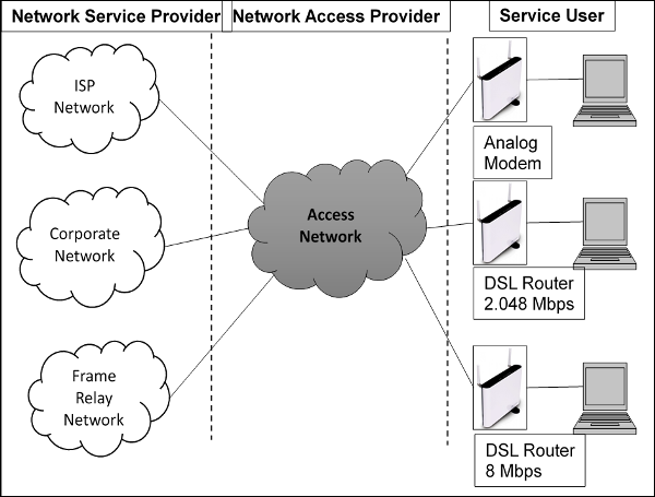
One of the compelling advantages of DSL technology is that it is the NSP and helps the Service Users to take full advantage of the existing infrastructure, layer two and layer three Protocols (such as Frame Relay, ATM and IP), and have reliable network services already entrusted to come.
DSL can easily support advanced business-class services such as Voice over DSL (VoDSL) and new variants of proven and well-understood technologies such as the Frame Relay over DSL (FRoDSL). The latest generation of DSL equipment also offers end-to-end Service Level Management (SLM). For simplicity, in our discussion regarding business class DSL applications, we will group all of these under a new acronym − SLM-DSL.
DSL - Basics
A wide range of DSL technologies and DSL products have entered the market, bringing with them both the opportunity and confusion. This chapter provides an overview of the technology, which can transmit information via copper lines and changing various DSL technologies. After understanding this concept, you can be better prepared to assess DSL technology and related products.
Basic DSL Concepts
The PSTN and supporting local access networks have been designed with guidelines that transmissions are limited to an analog voice channel 3400 Hz. For example − Telephones, Modems, Dial Fax Modem and Private Line Modems have limited their transmissions on local access telephone lines to the frequency spectrum between 0 Hz and 3400 Hz. The highest information rate possible using 3400 Hz frequency spectrum are less than 56 Kbps. So how does DSL achieve information rate in the millions of bits per second on the same copper lines?
The answer is simple − Eliminate the limit of 3400 Hz frequency boundary, much like the traditional T1 or E1, which uses a much wider range of frequencies than the voice channel. Such an implementation requires the transmission of information over a wide frequency range of one of the ends of the copper wire loop to another accessory, which receives the frequency width of the signal at the end of the copper loop.
As we have now understood that we can choose to remove the limit frequency 3400 Hz, and increase the supported information rate on copper son; you may be wondering, "Why not we just ignore POTS guidelines transmission and the use of higher frequencies?"
Attenuation & Resulting Distance Limitations
Let us understand regarding attenuation and the other factors that result in distance limitations.
Attenuation − The dissipation of the power of a transmitted signal as it travels over the copper wire line. In-home wiring also contributes to attenuation.
Bridged taps − These are unterminated extensions of the loop that cause additional loop loss with loss peaks surrounding the frequency of the quarter wavelength of the extension length.
Crosstalk − The interference between two wires in the same bundle, caused by the electrical energy carried by each.
One can compare the transmission of an electrical signal to drive a car. The faster you go, the more energy you burn over a given distance and the sooner you have to refuel. With electrical signals transmitted on a line of copper wire, the use of higher frequencies to support high-speed services also leads to shorter loop scope. This is because the high frequency signals transmitted by wire loops attenuate energy more quickly than low frequency signals.
One way to minimize attenuation is to use lower resistance wire. Thick wires have less resistance than thin wires, meaning lesser signal attenuation and therefore, the signal can travel a longer distance. Of course, thick gauge wire means more copper, which results in higher costs. Hence, the phone companies have designed their cable plant by using the thinner gauge wire that could support the required services.
Advanced Modulation Techniques Minimize Attenuation
In the early 1980s, equipment providers actively worked to develop basic rate ISDN, which provided up to 64 Kbps two B channels plus one D channel 16 kbps used for signaling and packet data. The payload of the information, and other overhead costs associated with the implementation, led to 160 Kbps in total transmitted information.
A key requirement of ISDN was that it had to reach customers on existing copper, equivalent to 18,000 feet. However, an AMI Implementation of basic rate ISDN would require the use of the lower part 160,000 Hz, resulting in too much attenuation of the signal and is below 18,000 feet, which is the necessary loop carried on the wire 26 gauge
In 1988, advances in signal processing and coding line has doubled the efficiency of the AMI code inheritance by sending two bits of information in each cycle of analog waveform or transmission. The line of code was called 2 binary, 1 Quaternary (2B1Q). A 2B1Q implementation of ISDN basic rate uses frequencies ranging from 0 (zero) to about 80,000 Hz, which has less attenuation and results in the desired loop reach of 18,000 feet.
History about ADSL Line Codes
Around the same time (1980s decade), the industry recognized asymmetric attributes of the local loop that telephone companies had developed a strong interest in providing video entertainment services. This interest has been motivated by the desire to increase revenue through new services and recognizing that non-US cable television operators have started offering voice services over their plant coaxial cable.
By late 1992, three line codes were emerging as the most likely technologies to support high-speed video dial tone services. These were −
QAM, or Quadrature Amplitude and Phase Modulation, a line coding technique used in modems for over 20 years.
CAP, which was introduced earlier for HDSL and is actually a variant of QAM.
DMT, or Discrete MultiTone, a line coding technique that was patented (but not implemented) by AT&T Bell Labs over 20 years ago.
Unlike 2B1Q, which is a baseband technology that transmits at frequencies, which include 0 Hz or DC, the line codes mentioned above are typically bandwidth and may be designed to operate in any frequency range specified.
DSL was originally designed as a residential service that needs to coexist independently with the POTS already provisioned. Therefore, the bandwidth attributes were considered a prerequisite for the frequency separation between FDM or POTS, a user upstream channel service on the network, and a downlink from the network to the user services.
In addition to the implementation of FDM above, some DSL technologies, including some implementations of DMT, were designed to provide an echo canceller of the upstream and downstream channels to minimize the use of frequencies more high and optimize loop reach. However, some observers believe that the performance of these systems echo canceled, tend to deteriorate. A growing number of similar services are deployed in the same cable bundle, offsetting the substantial gains associated with avoiding higher frequencies.
DSL - Home
DSL Home is an initiative taken by DSL-Forum. The following points will describe its various features and advantages.
To define requirements related to home devices like residential gateways, VoIP devices and local & remote management of home devices.
To enable triple/quad play services to the end-user(s) like voice, video, data, including IPTV, video on demand, content on demand, etc.
DSL Home remote management protocol (TR-69) and its extensions are access agnostic.
Remote Management is the core of DSL Home or next generation Residential Gateway (RG) & in-home networking.
DSL Home group has come up with the standards for CPE requirements and management of the CPE devices.
Standards defining requirements −
WT-124 − Issue 2 of TR-068 − Residential Gateway defining complete RG requirements that not specific to DSL but includes other access technologies like xPON.
TR-122 defines Voice ATA Requirements.
Standards in management framework −
TR-64 − LAN Side CPE Configuration and Enhancements.
For configuration and management of CPE devices via local LAN interface.
TR-69 − CPE Wan Management Protocol
For configuration and management of the CPE device through remote side.
TR-111 − allows TR69 remote management for the devices in the Home Network (HN).
TR-98 and TR-133 − Configuration and Management of Service differentiation (QoS) parameters in the CPE devices through TR-69 and TR-64 respectively.
TR-104 Data model for VoIP services
Extended for Video services too.
TR-106 defines the common data model template
Defines the baseline object structure and a set of accessible parameters for a TR-69 device.
TR-122 − defines Voice ATA Requirements.
WT-135 − object model for the STB devices.
WT-140 − object Model Network Storage Devices.
WT-142 − Framework for TR-069 enabled PON devices.
DSL Technology Options
The following table describes the various DSL Technology options in detail.
| Family | ITU | Name | Ratified | Maximum Speed capabilities |
|---|---|---|---|---|
| ADSL | G.992.1 | G.dmt | 1999 |
7 Mbps down 800 kbps up |
| ADSL2 | G.992.3 | G.dmt.bis | 2002 |
8 Mb/s down 1 Mbps up |
| ADSL2plus | G.992.5 | ADSL2plus | 2003 |
24 Mbps down 1 Mbps up |
| ADSL2-RE | G.992.3 | Reach Extended | 2003 |
8 Mbps down 1 Mbps up |
|
SHDSL (updated 2003) |
G.991.2 | G.SHDSL | 2003 | 5.6 Mbps up/down |
| VDSL | G.993.1 | Very-high-data-rate DSL | 2004 |
55 Mbps down 15 Mbps up |
| VDSL2 -12 MHz long reach | G.993.2 | Very-high-data-rate DSL 2 | 2005 |
55 Mbps down 30 Mbps up |
|
VDSL2 - 30 MHz Short reach |
G.993.2 | Very-high-data-rate DSL 2 | 2005 | 100 Mbps up/down |
Convergence at Home
Multiple broadband and networking technologies are converging in the next generation digital home, such as −
- ADSL2/ ADSL2 Plus / VDSL2 / xPON.
- Wireless/Ethernet/USB/HomePlug A/V, HPNA, etc.
- Consumer electronics begin to network.
Management of such convergence is complex, driving the need for simplification of end device provisioning and maintenance
Challenge − How to manage different elements within the home?
Solution − Essentially home networking represents a microcosm of all networking technologies and techniques that Conexant makes. Convergence is happening first in the home.
Today you need to be an IT expert (or have some teenagers in the house) to setup and configure your in-home networking devices. As addressed in the Industry, Applications and Technology Trends presentation, 30 − 50% of home networked devices are returned to the retailers with no trouble found. The users simply were unable to setup and configure the device using existing tools/software.
Problems with the Existing Approach
Following are the problems with the existing approach.
User Perspective
No flexibility to buy any equipment off-shelf.
No support from the service provider, if the equipment is bought.
Devices are not plug-n-play requiring both ISP & user to do some configuration.
Adding a new service requires both ISP & end-user coordination, which takes time.
Requires customer presence at home, if truck roll is involved.
Could be difficult to match as more couples are working nowadays.
Service Provider Perspective
Requires Truck Roll to activate any new services, troubleshooting and new installations. Each truck roll adds to a significant cost in terms of time and resources.
When customer lodges a complaint, then it is very difficult for the Helpdesk to verify what is wrong with the CPE device by sitting in their office.
Vendors provide their own proprietary solution, different interfaces, parameters and procedures. Hence the need for training per vendor solution.
ISP forced to stick with a few chosen vendors because ISP has done custom automation to make their job easier. Switching to a new vendor may require changing custom automation.
No way to discover the device-capabilities automatically and determine what parameters are supported.
Not possible to determine if user-changed configuration information via local management interface like Web, CLI, or SNMP, etc.
Not possible to prevent users from changing settings, which may affect the services offered by them.
Services Offered by DSL Home − TR-69
Following are the list of services Offered by DSL Home − TR-69.
Remote management of the devices in a secure manner (uses SSL/TLS based security).
Real-time provisioning of services via auto-configuration.
Status and performance monitoring.
Diagnostics
Access Control
Notification
Firmware upgrade
Standardized data model tailored specially for CPE devices offering various services like voice, video, data and IPTV, etc. Includes wide coverage for LAN devices in the home segments (STB, VoIP, NAS) on different LAN technologies like − Ethernet, USB, WLAN, etc.
Management protocol is to access technologies agnostics, thus it could be used for wide variety of CPE devices. For example − xPON, xDSL, etc., just requires the device to be IP addressable.
Truckroll is minimized by Remote management.
The Helpdesk can provide better services instead of just taking the complaint. Helpdesk has more context and can see complete configuration information about CPE from remote.
No need to have vendor-specific training as data model is standardized for services so less need of training the staff.
No custom automation required hence offering wider vendor base to choose from
Provides automatic discovery of parameters available on the device.
Provides Access control, hence allows prevention from user changing the specific configuration.
Provides Notification mechanism, thus we get to know any change in configuration related to the services.
Reduces Opex.
Making it easier for Users & Service Providers to move beyond modems and best effort routers to triple/quad play services in digital home.
TR69-Deployment Scenario
The following illustration depicts the TR69-Deployment Scenario.
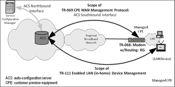
The TR69-Deployment will help with the following features −
A secure networking solution to serve simultaneous users within the home
Triple/Quad Play service (TV/video, telephony, Internet, wireless)
Real-time provisioning of services via auto-configuration
A mechanism to manage and automate support of such provisioning
The WT-124 => TR-068v2 adds new requirements that are based on expanded scope to include −
Optical (PON) WAN side Ethernet port requirements
Web redirection for diagnostic requirements
DHCP Client requirements
ACS initiated captive portal requirements.
Web redirection is needed when the network connectivity problems occur. The RG MUST provide a mechanism, which intercepts web browser pages (i.e. port 80 web page requests) and responds to these by directing the web browser to the appropriate internal web pages to identify and resolve network connectivity problems including, but not limited to −
DSL cannot train. − Q. How to get this from the appropriate PHY port to the web?
DSL signal not detected. − Q. Same question as above.
Broadband Ethernet not connected (if applicable).
ATM PVC not detected (if applicable).
IEE 802.1x failure (if applicable).
PPP server not detected (if applicable).
PPP authentication failed (if applicable).
DHCP not available.
Example − TR-069 Protocol Functioning
The following illustration depicts the functioning of the TR-069 Protocol.
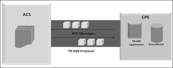
The above illustration is described in the following points.
The TR-069 enables the configuration and management of end-user devices (RG, STB and VoIP). A significant difference in the DSL Forum approach is that TR-069 can go directly to the end-user device.
Connection − Generic mechanism based on sending Remote Procedure Calls (RPC), which enables the ACS to read or write parameters to config, monitor and control the CPE. With RPC, SOAP messages (standard XML-based syntax), transported over a SSL/TLS (security layer), over HTTP, over TCP/IP connection, between CPE and a Management Server.
(Note) − SNMP sends Protocol Data Units (PDUs) on top of UDP between a manager and an agent. The UDP is unreliable when compared to TCP, PDU size limited to the UDP frame size.
ACS Discovery −
CPE can discover its associated ACS using DHCP.
Manual Configuration − CPE can be configured locally with the URL of ACS.
Default Configuration − CPE has a default ACS URL that it may use if no other URL is provided.
Session (Setup and teardown) − A session ALWAYS initiated from CPE to the ACS using the pre-determined ACS address: issues the Inform RPC method for setup and Session TearDown, which closes the TCP connection when done.
(Note) − SNMP does not support the concept of a session. Client needs to listen on a specified UDP port for messages from the server.
State Management −
For sequence of transactions forming single session, CPE maintains TCP connection that persists for duration of the session.
When continuous TCP connection not possible, ACS uses session cookies to maintain a session state.
CPE returns information (cookie) set by the ACS in all the messages exchanged. At the end of the session, CPE terminates the associated TCP connection to the ACS and discards all cookies.
Security
Security is enhanced with TR-069 by the CPE initiating all communication. The security TR-069 protocol supports following two security (level) mechanisms −
SSL/TLS defines a certificate-based authentication between the CPE and ACS to provide a single secure connection
The CPE can use the same x.509 certificate to provide encryption.
The client devices authenticated via the widely implemented HTTP authentication are as follows −
TR-069 and End Devices −
TR-069 can be used by ACS for managing −
Residential Gateways (RG)
End Devices (ED) based on TR-111
Two approaches −
RG acts as proxy for the ED
ED is managed directly by ACS
TR-111 defines extra rules that allow −
RG to discover TR-069 enabled EDs within the LAN
ACS contacts TR-069 EDs, even for non-TR-069 RGs (uses STUN; RFC 3489)
TR-064 LAN Side CPE
Following are the features of TR-069 LAN Side CPE Configuration.
Adopts the UPnP v1.0 architecture and extends the UPnP IGD v1 specification (with some restrictions).
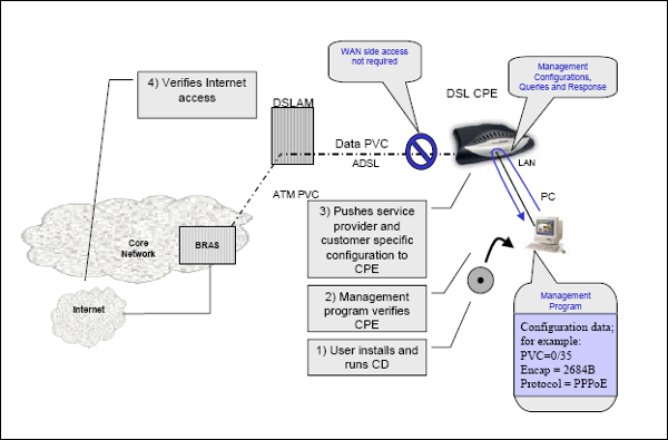
A management application (TR-64 control point) runs on a PC and it pushes service-provider and customer specific configuration to CPE, when the CPE adds to the network.
More useful during the initial installation of new CPE devices and when there is WAN side connectivity issues.
TR-64 Deployment Scenario
The following illustration depicts the TR-64 Deployment Scenario.
Use Cases for DSL Home Services
Let us consider the following Use Cases for DSL Home Services.
Use Case − 1
A customer buys broadband services initially for data and now needs to subscribe to VoIP services.
The customer can communicate the new services request via either SPs website or call up the office. In order to provide these services, the SP needs to address the following questions. Whether −
Option 1 − The existing CPEs hardware is capable of providing new services as requested.
Option 2 − Hardware is capable, but firmware needs an upgrade.
Option 3 − Both hardware and firmware are capable and it just needs VoIP service configuration.
Let us now understand each of the options in detail.
In the first option, the SP (service provider) either needs a truckroll to provide the VoIP capable CPE or can ask the user to buy the device from the market depending on the agreement they have.
For the second option, the SP can queue the firmware upgrade and VoIP configuration requests on the ACS for this CPE device. When CPE is switched on, it would automatically configured on the CPE via TR-69 and the ACS would be informed of the change. The Service Provider can configure the ACS to inform the user via-e-mail/SMS once it gets event for a successful configuration of the services.
For the third option, it just needs to queue the VoIP service configuration request on the ACS. When the CPE is switched on, the ACS would automatically update the configuration on the CPE device. The Service Provider can configure the ACS to inform the user via-e-mail/SMS once it gets event for successful configuration of the services.
Use Case − 2
The service provider is required to do firmware upgrade in bulk.
The SP has already deployed hundreds of devices and requires doing a firmware upgrade, because it is increasing the basic services level or finding a critical bug, which may affect the services in some way or the other. Let us consider the following points −
With the TR-69 management solution, the ACS shall have complete information about the CPE like the hardware version, firmware used on the devices (This information is passed by the CPE on each session setup).
The operator can identify the CPE devices, which may need an upgrade as not all device would need that.
From the ACS, it can schedule the firmware upgrade request to the selected CPEs in a staggered manner.
Once CPE firmware is updated, it shall get to know the list of CPEs on which the firmware was successfully upgraded.
All of this is happening without going out in the field from the comfort their own office.
Use Case − 3
Customer reports that Voice/Video service quality is not up to the mark.
This can be addressed by adhering to the following points −
Monitor the performance parameters that may affect the Voice/Video quality to troubleshoot and provide the expected quality of experience to the end customer.
In order to provide the differentiated services for Voice, Video and data, it can configure the desired QoS parameters as per the service level agreement with the customer.
Use Case − 4
Customer is facing connectivity issues and reports the problem with some services, then the service provider can −
The SP can run the diagnostics on the CPE to troubleshoot the issues.
It can set diagnostics parameter in the CPE and once diagnostics are complete, the ACS is informed of its completion. After that, the ACS can retrieve the results remotely through TR-69 and diagnose the issue.
Overall, the SP knows the cause without going out and hence can handle the situation more effectively.
DSL Home Roadmap
The following points describe the DSL Home Roadmap.
Interoperability of TR-069 −
Plugfest events − 3 are already done.
Last event saw participation of 22 CPE and 11 ACS vendors.
TR-069 or DSL Home certification under consideration.
A lot of WTs in progress: ACS northbound interface, new services object models, QoS, new RG specs, test & interoperability test cases, etc.
Align and liaise with UPnP Forum, DLNA, HGI, etc., defining standards towards the devices in home segments.
Quite a few standard bodies have accepted TR-69 standard for remote management of home devices: ITU-T SG16, Home Gateway Initiatives (HGI), ATIS IPTV Interoperability Forum (IIF), etc.
Direct Video Broadcast (DVB) organization (ETSI standards) adopted TR-069 and WT-135 for IPTV STB remote management or alternative from CableLabs.
ITU-T IPTV Focus Group involving multiple Study Groups will also be addressing remote management protocol issue.
TR-69 vs SNMP
The IETF (Internet Engineering Task Force) defines many MIBs to manage various features and the functionalities. However, there is no consolidation is done by any standard body or IETF recommending the use of a set of MIBs to manage the CPE (especially for Home Gateways providing Triple Play Service) devices for configuration and service provisioning. The MIBs support in a CPE device is totally left on the vendors to choose with respect to their own implementations. The TR-69 and other TRs under the DSL Home umbrella defines a set of parameters required on the CPE devices for such type of services. It recommends the set of parameters applicable for each type of services, which are −
Vendors are providing solution with their own proprietary MIBs thus making management of these devices vendor-specific.
No MIBs are available for system services like Firmware Upgrade, Diagnostics, etc., that is specific to CPE devices only.
Use of SNMP requires opening of SNMP port through NAT as most of the home gateways use NAT and the devices being managed could be behind NAT. In SNMP, the request to get/set any parameters is always initiated by the manager. Hence, the port has to be opened on the CPE to get the request. In TR-69, a TR-69 session is initiated by CPE and the server uses the same session to send get/set requests. That does away with opening of the port explicitly in the NAT environment. TR-69 also defines a way where ACS can send the request to CPE and this part is taken care by TR-111 part2 transparently.
Most of the SNMP implementations existing today do not implement SNMPv3. Hence, the messages exchanged over SNMP are not very secure. In TR-69, the security is taken care through the SSL/TLS or HTTP based authentication schemes. Most of the TR-69 implementations as of today implement SSL/TLS.
Any indication from CPE to the manager has to be dealt in terms of traps and these traps need to be predefined in the MIBs. Once these traps are defined, the manager cannot have a control on the CPE, whether it should or should not generate the trap on trap conditions. The TR-69 defines a very generic method for notification of any parameter change to the server. There is no need to define extra traps, this feature is built into the protocol itself and in case the manager does not need a notification of a parameter, they can switch it off by means of protocol. In addition, TR-69 provides for active or passive notification mechanism, which is missing in SNMP.
No access control mechanism for accessing a variable through another management protocol. TR-69 defines a mechanism in which it is possible to specify which management protocol can control which parameters and what level of access (read/read-write) is available to it. This feature is very useful when the service provider wants to control a set of parameters that, if changed, may affect the end-user services. SNMP does not define this level granularity.
Normally SNMP uses UDP as a communication mechanism, which is not very reliable, while TR-69 uses HTTP over TCP, which is more reliable.
On SNMP agents, the SNMP manager address and community string needs to be configured, while in TR-69 it is not mandatory to configure ACS specific parameters. ACS related parameters could be dynamically discovered through DHCP based mechanism, if not configured by the operator.
Through SNMP based management, the only actions supported are get/getnext and set from the manager. In case the management of the device requires some other proprietary action or downloading of a file, it cannot be done while in TR-69. This can be easily achieved by defining a vendor-specific RPC. Even the file download can be achieved in the same session between CPE and ACS with the use of existing RPC mechanism.
NO tailored MIB for CPE devices supporting Triple Play services.
Each vendor provides their own solution based on some std + proprietary MIBs
Use of SNMP requires opening of SNMP port on the device.
Most of SNMP based management does not implement SNMPv3. Hence, security is compromised.
Implementation for Notification on parameter change on any parameter is difficult.
No control on enabling and disabling of notification.
Provision for Access control is not there.
Usage of UDP based method for delivery, which is not very reliable.
Device could be managed by multiple managers at a time, which adds to the synchronization.
Only a specific set of actions could be supported.
Whatever could be achieved by SNMP can be achieved by TR-69 and many more.
Conclusion
Suite of DSL Home specs define next generation Residential Gateway (RG) solutions.
Making it easier for Users & Telcos to move beyond modems and best effort bridging/routing to triple/quad play services.
TR-069 (CWMP) is the core of DSL Home −
Extensible and flexible management protocol.
Access technology agnostic.
Active promotion of TR-069 for access technologies other than DSL. For example cable/DOCSIS, fiber/PON (WT-142).
Other bodies are adopting TR-069: ITU-T SG16 Q21, HGI, DVB, ATIS IIF, etc.
TR-068 (Modem with Routing) extended with WT-124 = RG box requirements.
TR-098 (RG data model) −
Rich modelling of RG QoS policy.
Adopted for HGI QoS.
No extensions needed in order to meet HGI requirements.
ACS simulation tool has been developed and is available to help customers in testing their CPE solution against an ACS.
In the next chapter, we will discuss the various DSL System Components.
DSL - System Components
In this chapter, we will discuss the Transport System, Local Access Network, Multiservice DSLAM, DSL Modem/Router and several other DSL System Components.
Transport System
This component provides the carrier backbone transmission interface for the DSLAM System. This device can provide service specific interfaces such as −
- T1/E1
- T3/E3
- OC-1
- OC-3
- OC-12
- STS-1 and
- STS-3.
Local Access Network
The local access network uses inter-CO local carrier network as a foundation. To provide connectivity between multiple service providers and users of multiple services, additional hardware may be required. Frame Relay switches, ATM switches and / or routers may be provisioned in the access network for this purpose. Increasingly, ILECs and PTO are looking for ATM equipment to fulfill this role, and next-generation DSLAM include ATM Switching to accomplish it.
Sometimes, it is instructive to consider the concept of an Access Node (AN), which is where the switches and / or routing equipment are physically located. Depending on the scale of the desired access network and the costs associated with transportation, we can expect to find one or more AN by local access network, creating an overlay structure on top of the inter-CO network. In some cases, the AN is integrated in the DSLAM, as is the case with the new generation of DSLAM that incorporate ATM switching systems.
Multiservice DSLAM
Residing in the CO environment (or in a space of near virtual collocation), the DSLAM is the cornerstone of DSL solution. Functionally, the DSLAM concentrates the data traffic from multiple DSL loops on the base network for connection to the rest of the network. The DSLAM provides Backhaul Services for the packet, cell and / or circuit-based applications through concentration DSL ON 10Base-T lines, 100Base-T, T1 / E1, T3 / E3 ATM or outputs.
Some DSLAMs are maintaining the temperature "hardened" for installation in areas that are not controlled environment. This allows the installation of the Remote Terminals in DSLAM or sidewalk cabinets instead of just in the central or virtual collocation spaces. The ability to move the DSLAM in these remote locations (with extended range loop technologies) can significantly increase the footprint of a service provider, for the provision of services to customers that would otherwise be out of reach of DSL
In addition to concentration and functions according to the specific service being provisioned, a DSLAM provides added features. The DSLAM may, in some cases be necessary to open the data packets to take action. For example, to support the dynamic IP address assignment using the Dynamic Host Control Protocol (DHCP), each packet must be considered in order to direct packets to the right destination (that is considered as a function DHCP-relay).
DSL Modem/Router
The criterion for assessment modem / DSL Router is the customer site equipment to connect the service user to DSL loop. The end point of DSL is generally 10/100Base-T, V.35, ATM or T1 / E1, along with the new generations of consumer products, which also support methods such as USB, IEEE 1394 (Firewire) and factor internal PCI form. In addition, CPE parameters are being developed with additional ports designed to support specific applications, such as RJ11 ports for support of voice (for e.g. IADs for service VoDSL), ports Video for video services based on DSL, and new networking interfaces such as Home Phoneline Networking Alliance (HomePNA) or wireless network such as 802.11 wireless Ethernet interfaces.
The DSL CPE devices are available in a number of different configurations depending on the specific service being provisioned. In addition to providing basic DSL modem functionality, many parameters have additional features such as bridging, routing, ATM multiplexing or TDM.
The Bridged Parameters serve the market well with ease of installation and maintenance. All work bridge setting device should have a learning filter to keep unwanted traffic crossing the network. Routed IP settings provide flexibility to the customer's site. With a point of IP-termination current, subnets can be created and maintained for effective segmentation of remote LAN and multicast and unicast downstream recognition.
Multiple service areas may also be used by remote users on the LAN at the same time. Several service areas become important when you have a large group of users who need access to various service providers such as the corporate LAN and the Internet through different ISPs.
The transparent protocol parameters behave like a DSU / CSU. They provide an interface for DSL link for routers and / or existing FRAD, which are Frame Relay Access Devices. Routers and FRAD manage the overall management of network traffic is plugged in, while the final point of DSL pass all traffic to the upstream DSL link.
The Channelized TDM parameters can function as DSU / CSU for T1 traditional service / E1. They also provide router interfaces, FRAD, multiplexers, PBX or any other device used to a traditional service.
The DSL modem / router must be designed, so that it can be installed with little or no required configuration. In addition, many service providers have demanded that the end of the DSL to be installed by the service user, requiring simply plug and play. DSL endpoint must be very manageable by the service provider.
Generally, the features search for the following points −
Ability to provide Layer 1 and 2 management statistics such as signal-to noise ratio.
Ability to provide Layer 3 MIB statistics such as packet counts.
Devices that are fully manageable by the service provider, without the need for on-site personnel.
Devices that support performance monitoring and end-to-end visibility for rapid fault detection, isolation and correction.
Ability to be remotely downloaded with new software as required.
Interoperability with third-party CPE including IAD.
POTS Splitters and Microfilters
The POTS splitters option lie in both the CO and service users slots, allowing copper loop to use for media transmission, simultaneous DSL high-speed data and the single line telephone service, when the DSL variant uses these services.
POTS splitters generally come in two configurations −
A single separator version designed for mounting to the residence and
A multiple release separator designed for the ground connection to CO.
Note that, while the number of DSL line coding systems support only one channel POTS, others do not. Services Reference Schema-based DSL POTS splitters can be either passive or active. The active POTS splitter requires an external power source for voice and DSL to run on a single copper pair. The passive POTS splitter requires no power and typically have a higher MTBF (Mean Time between Failures) as its active counterpart. While passive POTS splitter supports vital services such as 911 in case of power loss DSLAM or DSL modem, the active POTS splitter should have a backup power supply to provide these essential services in the event of power loss.
The DSL as G.dmt ADSL, G.lite, RADSL ReachDSL and can be installed today without POTS CPE separate separator. Instead, passive devices known as micro-filters can be installed between each user POTS device in the customer's premises (such as telephones, analog modems and fax machines) and wall outlets. Microfilter is a filter "low pass" that allows voice-band services to be transmitted, while filtering the high frequencies used by DSL and eliminates interference.
The advantage of this approach is that while traditional POTS splitters were installed on the Network Interface Device (NID) by a service provider installer, micro-filters can be easily connected to the end user, eliminating the need for a service call for the installation. For a DSL service that runs on the POTS connection is always the first choice for the installation.
DSL - ADSL Fundamentals
In this chapter, we will discuss the fundamentals and standards of Asymmetric Digital Subscriber Line.
ADSL Fundamentals
To begin with, let us understand the following points.
Discrete Multi-Tone (DMT) modulation used by all ADSL standards for a physical layer.
Divide the frequency band into many small channels.
QAM modulation on each channel.
Different bits assigned to each channel in terms of SNR.
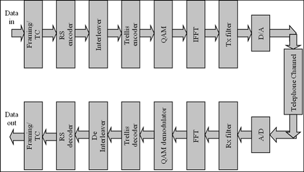
ADSL Fundamentals System Block Diagram for PHY
Following is the ADSL Fundamentals System Block Diagram for PHY.
ADSL Standards
The following table describes the ADSL Standards.
| Version | Standard name | Common name | Downstream rate | Upstream rate | Approved in |
|---|---|---|---|---|---|
| ADSL | ANSI T1.4131998 Issue 2 | ADSL | 8.0 Mbit/s | 1.0 Mbit/s | 1998 |
| ADSL | ITU G.992.1 | ADSL (G.dmt) | 8.0 Mbit/s | 1.3 Mbit/s | 1999-07 |
| ADSL | ITU G.992.1 Annex A | ADSL over POTS | 12.0 Mbit/s | 1.3 Mbit/s | 2001 |
| ADSL | ITU G.992.1 Annex B | ADSL over ISDN | 12.0 Mbit/s | 1.8 Mbit/s | 2005 |
| ADSL | ITU G.992.2 | ADSL Lite (G.lite) | 1.5 Mbit/s | 0.5 Mbit/s | 1999-07 |
| ADSL2 | ITU G.992.3 | ADSL2 | 12.0 Mbit/s | 1.3 Mbit/s | 2002-07 |
| ADSL2 | ITU G.992.3 Annex J | ADSL2 | 12.0 Mbit/s | 3.5 Mbit/s | |
| ADSL2 | ITU G.992.3 Annex L | RE-ADSL2 | 5.0 Mbit/s | 0.8 Mbit/s | |
| ADSL2 | ITU G.992.4 | splitterless ADSL2 | 1.5 Mbit/s | 0.5 Mbit/s | 2002-07 |
| ADSL2+ | ITU G.992.5 | ADSL2+ | 24.0 Mbit/s | 1.4 Mbit/s | 2003-05 |
| ADSL2+ | ITU G.992.5 Annex M | ADSL2+M | 24.0 Mbit/s | 3.3 Mbit/s 2008 | 2008 |
| ADSL2++ | (up to 3.75 MHz) | ADSL4 | 52.0 Mbit/s ? | 5.0 Mbit/s | In development |
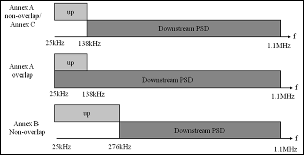
Annexure G.DMT
G.992.1 Annex A − Full rate ADSL over POTs
- Overlapped Spectrum PSD Masks
- Non-overlapped Spectrum PSD Masks
G.992.1 Annex B − Full rate ADSL over ISDN
- Overlapped Spectrum PSD Masks only, however, overlap is optional
G.992.1 Annex C − Full rate ADSL in TCM-ISDN binder
- PSD Mask as for G.992.1 Annex A
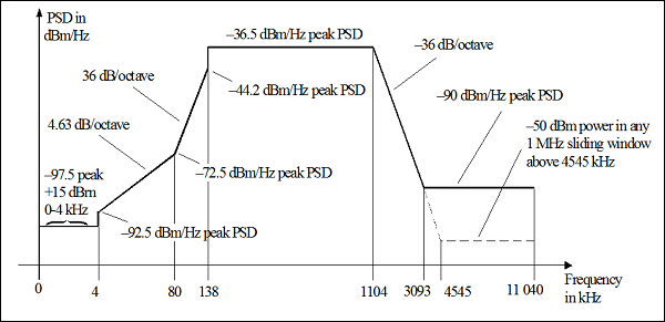
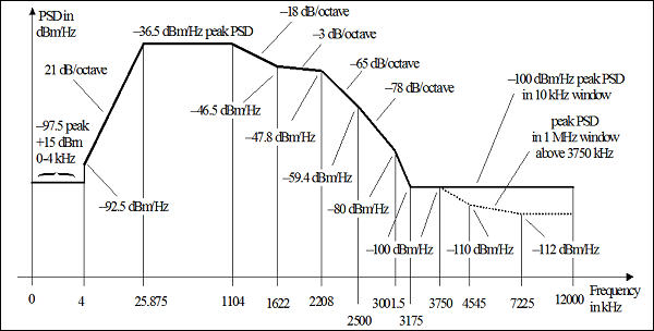
G.DMT PSDs
The following illustration describes G.DMT PSDs.
G.Dmt Performance
The G.Dmt Performance can be understood by the following description.
- NSC = number of sub carriers
- Sub carrier spacing = Δ f = 4.3125 KHz
- Data symbol rate = 4.0 KHz
- Data rate = N * 4 * 8 Kbps (multiples of 32 Kbps)
- Bandwidth = NSC * Δ f
- Sample rate = 2* NSC *Δ f
NSC                                 256
Total bandwidth                     1.1 MHz
Sample rate                         2.2 MHz
Maximum Date Rate                   ~12Mbps(down)/1.2Mbps (up)
Maximum Reach                       20kf
Dial Tone Services
While DMT was chosen as the official standard, systems based on the CAP have been used worldwide to implement many ADSL and a line of video sounds trials and commercial deployments, determine effectively the CAP as a de facto standard ADSL competition. Meanwhile, the threat of offering telephony services in the industry of cable television in the United States largely subsided.
Globally, the tone video applications have increased, but continues to maintain interest. In many markets, they were difficult to justify the cost in relation to the widespread availability of cable TV and satellite TV.
As a result, the video dial tone initiatives have largely disappeared in North America. The final standard for ADSL - approved by the International Telecommunication Union (ITU) (G.dmt or G.992) and ANSI (T1.413 Issue 2) was, as mentioned earlier, a DMT-based system and is the basis of most new ADSL deployments today. Some vendors, however, continued to deploy PAC-based systems in their networks.
Application Switch from Video to Data
Throughout these long tone trial video dialing, the industry has come to recognize that many data applications were made asymmetrical. The best example of this is the internet. Typically, users send a small stream of data to a remote server, which requests the download of a data file, graphic, audio and video in particular. In response, the server starts sending the file data rate that can be supported over the network to the remote workstation. This transaction is extremely asymmetrical in nature.
During this same time, the Internet has evolved into a completely new phenomenon, which is unheard of, when compared to the rate of the new subscribers to the Internet growth services. The biggest complaint of all users is that it took too long to upload files to the modem dial or even ISDN data rates. Therefore, a new need of services and new technology were soon married, and ADSL has been reoriented to support Internet access.
Video has not completely disappeared as a request for DSL. However, video delivery over IP − using systems such as RealMedia or Windows Media has become increasingly popular and sophisticated. Using compression systems such as MPEG-2 or new industry standard systems that allow even compression of the video, IP video delivery continues to be a viable application for DSL.
Optimization for Data Services
When the application was a bit synchronous video, the DSL line had to run at a specified line speed. However, the data can be operated at a wide range of speeds. The only effect is that slower speeds take longer to transport large files. Therefore, with data applications, we have the possibility of reducing the line speed to allow the service to be provisioned over longer lines. Both CAP and DMT transceivers have been modified to optimize the service on a loop basis and its implementation was called Adaptive Rate Digital Subscriber Line, or RADSL.
RADSL technology supports the ability to allow the transceiver to automatically-increase the line speed to the highest achievable data rate, which can be achieved reliably over a given loop. Although this feature was designed primarily to simplify the service facility, it also gives service providers the possibility of a graceful degradation of service in case of degrading loop conditions. Today, there are other DSL technologies, which support the adaptation of rates. The service providers interested in this feature should examine the extent to which it is supported in different technologies.
RADSL Standards
As it can be seen, industry and technology have changed dramatically since the tone Video ADSL standards decision in March 1993. In recognition of this Working Group, T1E1 ANSI has established a standard known as ANSI TR59 RADSL. The FCC has specifically cited RADSL as a technology that is spectrally compatible with voice and other DSL technologies in the local loop.
IDSL Provides DSL over ISDN
In some cases, DSL concepts have been applied to existing technologies. For example, ISDN DSL or IDSL, first emerged as a new spin technology of the 1980's just IDSL ISDN CPE (customer premises equipment) talking to ISDN-compatible line cards that located on the other end of the copper wire loop and terminate the ISDN signal independent of the telephone switch.
In this scenario, as with all DSL variants, the data service is directed to an extended data service, rather than of a switched network. While IDSL is based on proven technology, it is functionally an ISDN subset in that it waives any possibility to support the switched telephone service and connectivity in general. A key advantage of IDSL is the service provider seeking to move long-term ISDN data connections to Internet servers or remote LAN access off the switched network. Another key benefit is that because IDSL uses ISDN signaling methods, it is capable of transmitting over copper pairs that are served by digital loop carriers.
These devices, which are remote terminals designed to extend the reach of POTS and ISDN services beyond the usual scope of central office on completion of the copper lines, are often connected to the central office by the fiber optical private line and, as such, cannot carry any type of ADSL and SDSL DSL signals.
Multirate Symmetric DSL
Beyond the bandwidth of 144 Kbps provided by IDSL, there are new technologies that have emerged that can be better-classified office / small office and residential home (SOHO) possibilities. These technologies offer operating ranges between 128 Kbps and 2.048 Mbps.
For symmetric applications, Multirate SDSL (M / SDSL) has emerged as a valuable technology to meet the requirements of carriers to deliver Time Division Multiplex (TDM) services on an almost ubiquitous base. Based on the single pair SDSL technology, M / SDSL supports changing rate of command line transceiver and thus the operating distance of the transceiver. This version of CAP supports eight separate rates for a service 64 Kbps / 128 Kbps to 29 kft (8.9 km) 24-gauge wire (5mm) and 15 kft (4.5 km) at a speed of 2 Mbps in full. With a capacity of AutoRate (similar to RADSL), symmetric applications can now be universally deployed.
G.lite for the Consumer Market
In January 1998, the Universal ADSL Working Group (UAWG) was announced. It composed of large organizations in the telecommunications, networks and personal computers. This group was formed to develop low speed and the alternative cost of ADSL that could be installed, while the consumers were rapidly deployed by service providers. The result of the work of this group is a new subset of ADSL G.lite based standards.
G.lite was approved as a standard by the ITU (G.992.2) in June 1999 and can offer speeds up to 1.5 Mbps downstream and 512 Kbps upstream. Significantly, G.lite was designed to provide this service on existing telephone lines without the POTS splitter usually required by ADSL solutions at the full rate. A part of the G.lite, standard is as "fast retrain" known technique which limits the input power of the G.lite signal, when a telephone handset is in use. This helps to minimize interference and restore power, when the phone is back on the hook.
ReachDSL Benefits
Following are the benefits of ReachDSL.
Splitterless installation − No POTS splitter is required at the customer premises, simplifying installation and allowing customer self-installation.
Greater loop reach − In addition to ADSL systems, which can generally reach distances below 18,000 feet from the central office, the ReachDSL systems extend well beyond services 20,000 feet, with some power plants above 30,000 feet as well.
Spectral compatibility − ReachDSL solutions offer superior spectral compatibility. A member of the family ReachDSL, MVL (multiple virtual lines), was the first DSL system recognized by the FCC in section 68 approval, which means that it is "friendly" to other services over the telephone network and not a jammer. ReachDSL also operates in spectrum management class to offer better range and higher speed.
Lower product cost − ReachDSL products utilize "off the shelf" rather than customized Digital Signal Processors (DSPs).
Dynamic bandwidth allocation − Allows the service to be customized for different applications.
VDSL Delivers Video and Higher Bandwidth
There are new variants that are emerging like VDSL, DSL, or DSL high speed. VDSL systems are still being developed, so that the final capacity is not yet well established, but the proposed standards require downstream bandwidths up to 52 Mbps symmetrical bandwidth up to 26 Mbps. The compromise in these bandwidths is a shorter loop section, often as short as 1000 feet for higher bandwidths possible bands, with adaptation of speed at lower speeds than the length of the loop increases.
Given these limitations, VDSL deployments are planned to use a slightly different model than the traditional DSL, DSLAM with the move out of the central office of the telephone company and the neighborhood, with lines of optical fibers supplying local cabinets containing DSLAM.
The high speeds offered by VDSL bring opportunities for service providers to deliver the next generation of DSL services, with the video being considered as a first application. At 52 Mbps, a VDSL line can offer a customer complete multi-channel MPEG-2 video stream quality and even offer one or more television channels in high definition full quality (HDTV).
Some service providers have started VDSL systems deployment tests that provide these services with the endpoint VDSL appearing in the residence as a set-top box such as cable TV with an Ethernet or other data interface for connection to a PC for simultaneous data services.
The basic principle of DSL is a local loop technology in which compatible devices reside on each end of a single copper wire loop ensures that new DSL technologies continue to emerge over time. A strategic point for the service provider is to ensure that the selection of a specific technology or DSL network model for the deployment of services today will not limit options to adopt new technologies in the future.
Why ADSL2?
The following points describe why ADSL2 is so favorable
ADSL provides up to 8Mbps/800Kbps data rate (possibly 12M/1.2M).
Reach of 18-20kf 26AWG (about 6000m).
No seamless rate change.
No power saving mode when there is no user activity.
No 1-bit per bin and partial byte per symbol.
Fixed 64Kbps overhead channel rate (Framing Structure3).
ADSL2/ADSL2+
The following points describe the various features of ADSL2/ADSL2+.
ADSL2+ provides up to 24Mbps/1Mbps data rate.
Seamless rate adaptation when SNR change.
Power Management greatly reduce power consumption.
1-bit per bin and partial byte per symbol improves reach.
Reach of 20-22kf 26AWG (about 7000m).
Variable overhead channel rate meets user need.
Loop diagnostic function during training.
ADSL2/2+ Benefits
ADSL2 and ADSL2+ Delivers next generation features to improve the DSL deployment business case. Following are some of its benefits −
- Higher Rates
- Extended Reach
- Improved Stability
- Power Management
- Enhanced Spectral Compatibilit
Extended Reach
ADSL2 enables service providers to extend existing rates plans at longer loop lengths using rate enhancement technologies −
Rate Enhancement Technology −
- Reduced framing Overhead
- Mandatory Trellis Coding
- 1-bit constellations
- Data on pilot tone
Long Reach DSL (LDSL) −
- RE-ADSL2 Boosted PSD for North America
- Overlapped Mode
Framing Enhancement
The following features help in framing enhancement.
More flexible framing structure
Replaced Framing Structure types 0, 1, 2 and 3 in G.DMT
Receiver selects configuration parameters
Optimal Reed-Solomon coding possible
Configurable overhead channel from 4Kbps to 64Kbps
HDLC based OAM protocol to retrieve detailed performance monitoring information.
PMD Enhancement − Training
The following features help in PMD enhancement − training.
New line diagnostic procedures.
Receiver selects pilot tone.
Improved SNR measurement during channel analysis.
Improved exchange of detailed transmit signal characteristics.
Tone blackout to allow RFI measurement during initialization.
PMD Enhancement − Performance
The following features help in PMD enhancement − performance.
Mandatory support of trellis coding.
Mandatory support of one-bit constellation.
Data modulated on pilot tone.
Improved RFI robustness with receiver determined tone ordering.
PMD Enhancement − Power
The following features help in PMD enhancement − power.
Transmit power cutback.
Mandatory transmit power reduction.
Power saving feature for ATU-C with new L2 low power state.
Power saving feature with new L3 idle state.
PMD Enhancement Dynamic
The following features help in PMD enhancement dynamic.
Bit-swapping
Seamless Rate Adaptation (SRA)
Dynamic Rate Repartitioning (DDR)
WHY On-Line Reconfiguration?
The following points describe why OLR is required.
DSL line condition changes all the time crosstalk, weather, radio, environment, etc.
User activity changes all the time on/off hook, peak/normal usage.
Operator bandwidth re-allocation.
On-line Reconfiguration (OLR)
The following points tell us regarding OLR
Maintain seamless operation when line or environment are slowly changing.
Optimize rate setting (6dB margin could be reduced).
Upper layer provisioning provided.
All channels can operate independently.
Types of On-line Reconfiguration
Following are the types of OLR.
Bit Swapping (BS) −
- Relocates data and power among sub-carriers
- Adapt varying line condition
Seamless Rate Adaptation (SRA) −
- Reconfigure the total data rate
- Background SNR monitoring can find optimal setting
Dynamic Rate Repartitioning (DRR) −
- Reconfigure the data rate allocation between multiple latency paths.
Control Parameters
Following are the control parameters for Framer Configuration and PMD Function.
Framer Configuration −
Bpn − The number of octets from frame bearer #n in latency path #p.
Lp − The number of bits per symbol from latency path #p.
PMD Function −
- bi, gi
- L − Total data rate
Improved Stability with SRA
Seamless Rate Adaptation (SRA) enables the modem to change rates and bit loading to maintain a minimum per bin margin without re-training.
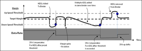
GlobespanVirata Inc.s ADSL2 compliant SRA can change individual bins or all bins at once. It enables rate changes & noise adaptation in seconds instead of minutes.
Summary of OLR
The following table describes the summary of OLR.
| Type | Changing Parameters | Initiating | Optional | Comments |
|---|---|---|---|---|
| BS | bi, gi | Receiver | No | Changing line condition |
| DRR | bi, gi, Bpn, Lp | Receiver Transmitter |
Yes | Higher Layer |
| SRA | bi, gi, Bpn, Lp, L | Receiver Transmitter |
Yes | Higher Layer |
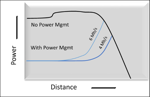
Power Management
The following points describe the power management in OLR
DSLAM power consumption at KW level and 24/7.
Lot of power can be saved.
Around -40 dB TX power cut back saves 100mW per port.
The 2000 port DSLAM can save 200W!
Maximum Margin Algorithm
The benefits of maximum margin algorithm of OLR are as follows −
Eliminates excess margin on the line.
Estimates line conditions and backs off Tx power during handshake.
Compatible with Legacy CPEs.
Cuts Line driver power up to 60% on typical loops.
Statistical Power Management
It reduces overall power up to 50% during customer idle periods.
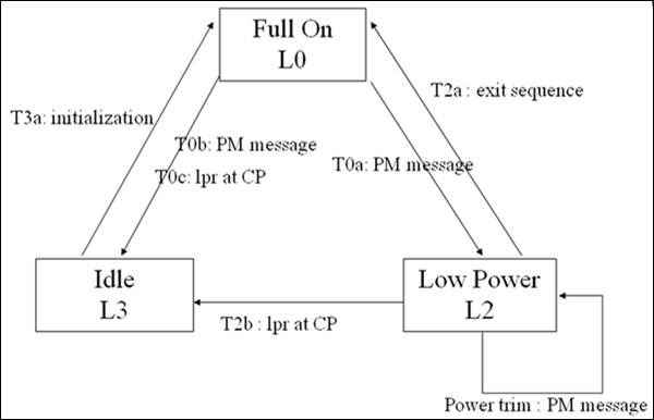
Objectives
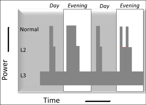
The main objectives are Power Saving and cross-talk minimization. There are three Power Management states −
L0 − full power data mode (as we have today)
L3 − idle mode (not attempting to start)
L2 − low power mode by −
Increasing power cutback value (<40dB)
Low bit rate
Higher Rated ADSL2+ Technology
The higher rated ADSL2+ technology enables the following −
Enables higher rates for premium data, voice and video deployment.
Enables data rates up to 26 Mb/s.
Extends reach of 10-12Mb/s by up to 2x over ADSL S=1/2
Optional remote bandplan enables deployment from Remote Cabinets without degradation of services from the CO.
Individual bin disabling provides full compatibility with legacy services.
Auto-Detection of CPE capability enables compatibility with legacy CPEs
ADSL/ADSL2 ATU-C TX Spectrum
The following illustration depicts the ADSL/ADSL2 ATU-C TX Spectrum.
ADSL2+ ATU-C TX Spectrum
The following illustration depicts the ADSL2+ ATU-C TX Spectrum.
ADSL2+ Features
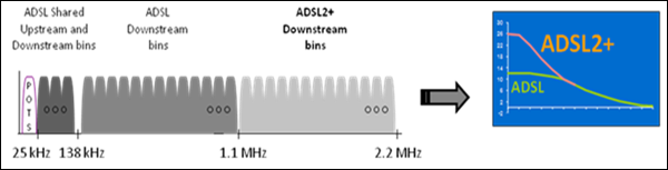
Following are the features of ADSL2+.
Doubles downstream spectrum from 1.1MHz to 2.2 MHz with downstream bin number increased from 256 to 512.
Maximum downstream data rate increase from 8Mbps to 24Mbps.
Improved performance at short loop length.
Wider range for SRA and Power Management from 32Kbps to 24 Mbps.
ADSL2+ Performance
The following points describe the performance of ADSL2+.
ADSL+ and ADSL2+ enable high-speed asymmetric DSL applications as well as the traditional long reach DSL services.
Auto-Detection enables fallback to ADSL2 and legacy ADSL.
ADSL2+/ G.Span enable 22/3 service without VDSL 1.5km reach limitations.
Interoperable with legacy ADSL CPEs.
Range Extended DSL (RE-ADSL)
Range Extended ADSL (RE-ADSL) is Annex L of G.992.3
Reach extended by 1- 2 kft
The foundation of the specification has a mandatory non-overlapped PSD definition together with an optional overlapped PSD definition.
Annex M
- Introduce to improve upstream rate
- Maximally double the upstream bins
- At cost of downstream if non-overlapping
- Up to 3Mbps upstream data rate
The following table describes the various aspects of ADSL.
| ADSL 1 | ADSL2 | ADSL2+ | |||
|---|---|---|---|---|---|
| Reference | ITU G.992.1/T1.413 | ITU G.992.2.3 | ITU G.992.5 | ||
| Annexes | Annex A | Annex A | Annex L | Annex M | Annex A |
| Nickname | G.DMT | BIS | RE-ADSL | Annex M | BIS+ |
| Number of bins | 256/32 | 256/32 | 128/32 | 256/64 | 512/32 |
| Max downstream rate | 12Mbps | 12Mbps | Max reach, 22kf | ~10Mbps | 26Mbps |
| Max upstream rate | 1.2Mbps | 1.2Mbps | 3Mbps | 1.2Mpbs | |
| Advantage | early version of ADSL | QOS, Power, Reach | reach | higher upstream | higher downstream |
DSL - VDSL Access Technology
VDSL is the technology with a high rate. Operating at speeds up to 52Mbps, VDSL is the next generation of DSL technology with higher throughput and requirements for implementing, which are simpler than ADSL. VDSL began its life being called VADSL, but was renamed VDSL by the ANSI working group T1E1.4. The main reason T1E1.4 decided VDSL on VADSL was that, unlike ADSL, VDSL is both symmetric and asymmetric. VDSL is nearly ten times faster than ADSL and is over thirty times faster than HDSL. In the tradeoff for increased speed loop length: VDSL has a shorter reach in the loop.
In the following table, it shows a comparison of the various DSL technologies available today. We see that VDSL is highest in terms of bandwidth technology and supports applications both asymmetric and symmetric, and is ideal for broadband full service.
| DSL Type | Symmetric/ Asymmetric | Loop Range (kft) | Downstream (Mbps) | Upstream (Mbps) |
|---|---|---|---|---|
| ISDL | Symmetric | 18 | 0.128 | 0.128 |
| SDSL | Symmetric | 10 | 1.544 | 1.544 |
| HDSL (2 pairs) | Symmetric | 12 | 1.544 | 1.544 |
| ADSL G.lite | Symmetric | 18 | 1.5 | 0.256 |
| ADSL | Asymmetric | 12 | 6 | 0.64 |
| VDSL | Asymmetric | 3 | 26 | 3 |
| Asymmetric | 1 | 52 | 6 | |
| Asymmetric | 3 | 13 | 13 | |
| Asymmetric | 1 | 26 | 26 |
Like other DSL technologies, VDSL uses higher frequency spectrum of copper above standard frequencies used for lifeline service to the plain old telephone (POTS) and Integrated Services Digital Network Services (ISDN). This is commonly referred to technology as data and video-on-voice. This technology enables Telcos existing copper infrastructure for the provision of broadband services over the same physical plant.
VDSL spectrum is specified to range from 200 kHz to 30 MHz. Real spectral distribution vary with the line rate or based on asymmetric or symmetric rates that are used. Baseband for POTS and ISDN service use is preserved by the use of passive filters commonly called as dispatchers.
Asymmetric VDSL
VDSL is designed to offer a multitude of asymmetric broadband services, including Digital Television Broadcasting, Video on Demand (VoD), High-Speed Internet Access, Distance Learning and Telemedicine, to name a few. The delivery of these services requires the downstream channel to have a higher bandwidth that the channel upstream and is asymmetrical.
For example, HDTV requires 18 Mbps for video content downstream. Upstream, however, it does not require the transmission of signaling information (e.g., change of channel or program selection), which is of the order of kbps.
The following table specifies the rate VDSL standards established in the specification / ANSI S1.4 of T1. The downstream rates are derived from the sub-multiples of Synchronous Optical Network (SONET) and Synchronous Digital Hierarchy (SDH) speed of 155.52 Mbps canonical, i.e. 51.84, 25.92 Mbps and 12 Mbps, 96 Mbps.
| Typical Service Range | Bit Rate (Mbps) | Symbol Rate (Mbps) | Comments |
|---|---|---|---|
| Short range, 1 kft | 6.48 | 0.81 | baseline |
| 4.86 | 0.81 | optional | |
| 3.24 | 0.81 | ||
| Medium range, 3 kft | 3.24 | 0.405 | baseline |
| 2.43 | 0.405 | optional | |
| 1.62 | 0.405 | ||
| Long range, 4.5 kft | 3.24 | 0.405 | baseline |
| 2.43 | 0.405 | optional | |
| 1.62 | 0.405 |
Symmetric VDSL
VDSL is also designed to provide symmetrical services for small and medium business customers, business enterprise, high-speed data applications, video conferencing and tele-applications, etc.
Symmetric VDSL can be used to provide short-haul T1 replacements NXT1 rate and support a host of other business applications.
The following table contains the symmetric VDSL standards for service established in the ANSI T1E1.4. A rate of 6.48 Mbps to 25.92 Mbps, it should be noted that VDSL provides symmetrical service between the standard T1 (1.536 Mbps) and T3 (44.376 Mbps) rates, fill the gap simplest copper twisted pair. Although ANSI has not specified distance and long-term rates for symmetric services 6 Mbps to 1.5 Mbps on loops from 3 kft to 10 kft may be supported.
| Typical Service Range | Bit Rate (Mbps) | Downstream Symbol Rate (Mbps) | Upstream Symbol Rate (Mbps) |
|---|---|---|---|
| Short range, 1 kft | 25.92 | 6.48 | 7.29 |
| 19.44 | 6.48 | 7.29 | |
| Medium range, 3 kft | 12.96 | 3.24 | 4.05 |
| 9.72 | 3.24 | 2.43 | |
| 6.48 | 3.24 | 3.24 |
DSL - VDSL-based Service Sets
VDSL offers a variety of simultaneous services, which are not possible otherwise. This opens the possibility for service providers to offer a new base for your subscription and multimedia services. Telco providers offering telephony and data services can now expand their business by offering comprehensive services and a host of video-centric applications. This enables the telecom companies to compete with television operators by effective invasive cable.
The original charter for ADSL was to provide a full range of broadband services for residential consumers, so why the need for VDSL? The reality is that ADSL is an Internet technology only.
The following table illustrates that, in the end, ADSL is limited in its ability to provide a full range of broadband services. VDSL, on the other hand, is well suited to provide these services today and tomorrow
| Application | Downstream | Upstream | ADSL | VDSL |
|---|---|---|---|---|
| Internet Access | 400 kbps − 1.5 Mbps | 128 kbps − 640 kbps | yes | yes |
| Webhosting | 400 kbps − 1.5 Mbps | 400 kbps − 1.5 Mbps | today only | yes |
| Video Confrencing | 384 kbps − 1.5 Mbps | 384 kbps − 1.5 Mbps | today only | yes |
| Video on Demand | 6.0 Mbps − 18.0 Mbps | 64 kbps − 128 kbps | today only | yes |
| Intractive video | 1.5 Mbps − 6.0 Mbps | 128 kbps − 640 kbps | today only | yes |
| Telemedicine | 6.0 Mbps | 384 kbps − 1.5 Mbps | today only | yes |
| Distance learing | 384 kbps − 1.5 Mbps | 384 kbps − 1.5 Mbps | today only | yes |
| Multiple Digital TV | 6.0 Mbps − 24.0 Mbps | 64 kbps − 640 kbps | today only | yes |
| Telecommuting | 1.5 Mbps − 3.0 Mbps | 1.5 Mbps − 3.0 Mbps | no | yes |
| Multiple VoD | 18 Mbps | 64 kbps − 640 kbps | no | yes |
| High-definnition TV | 16 Mbps | 64 kbps | no | yes |
DSL - VDSL-based Video Service
VDSL provides operators the ability to offer a multitude of digital video service that increases their phone deals and existing Internet services. VDSL has the capacity to support Digital Television Broadcast, Video on Demand, and HDTV over standard twisted-pair copper.
In addition to digital video and Internet services, VDSL also supports interactive video services, Web TV, e-commerce, video conferencing, and video games, which is a set of services currently not available from cable operators or DBS.
High-Speed Internet
Providing access to high speed Internet is an essential value for home users, small businesses, hotels, institutions and other multi-site buildings. The Internet is growing at a phenomenal rate and this growth is the expansion of new and varied applications to take advantage of the increased availability of equipment, software, access, and users. These new applications require more resources than can be provided with the existing infrastructure, which limits the profit potential in providing these applications.
While other DSL technologies such as ADSL and G.lite, can meet the limited requirements of Internet applications today. These systems will soon run out of bandwidth. However, VDSL has the capacity to support today's applications with dining support emerging applications of tomorrow, creating new revenue growth opportunities, while preserving investment in DSL technology.
As the Internet grows increasingly architecture backbone is replaced by ATM. ATM technology is the preferred Internet backbone FSAN to manage the growing burden to support daily operations and mission critical applications. The ATM architecture was chosen because it allows a single ATM network to be used to support all data transport, voice and video instead of delivering them to separate and incompatible networks. The combination of VDSL and ATM technology provides Internet services today in an architecture that supports the applications of tomorrow.
Telephony Services
A key service for every telco is the delivery of lifeline telephony services. One thing that has become universally expected is that no matter what, the phone will work. VDSL, like other DSL technologies, supports a lifeline POTS connection. This is a basic requirement that must be met by a telephony service provider. VDSL offers this feature and gives the telco opportunity to provide additional voice channels derivatives on the same pair of existing copper.
The Voice over IP (VoIP) and Voice over ATM (VToA) technologies are providing standard quality telephony services over a digital network. Because ATM can also transport communications based on IP, ATM over VDSL will support both digital telephony standards. Although Voice over DSL (VoDSL) initiatives seek to develop a standard for carriage on flavors of DSL, bandwidth is always the question. Higher bandwidth VDSL provides more derived voice channels.
Cable operators are starting to enter the market of voice using these technologies, but they face a major obstacle in providing Lifeline Services. The capacity of the new class of telecom operators offering comprehensive services to provide lifeline POTS along the derivative telephony, Internet access, and digital video services is a key advantage over cable and DBS operators.
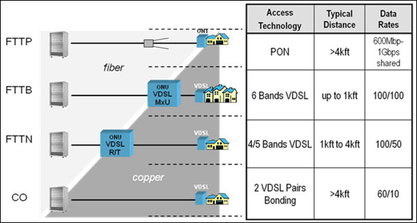
Deployment Scenarios
The deployment of the full service access network is progressing with the deployment of fiber-based networks. The final architecture is fiber-to-the-home and business, but it will take a number of years and significant resources to implement.
Deployment scenarios for today are the fiber-to-the-trade (FTTEx), fiber-to-theneighborhood (FTTN), FTTCab and FTTB. VDSL is only suitable for FTTEx, where customers are served within reach of the central exchange (CO). FTTN and FTTCab are suitable for standalone deployments, VDSL switch or as part of a New Digital Loop Carrier Generation (NGDLC).
FTTB would bring fiber directly into a building like a multi-site unit (MDU) or business of the company and end the VDSL.
Major VDSL2 Activity
Following are the countries, which are using VDSL2.
Taiwan
Presently, 5-band 100/50Mbps and 30MHz 100/100M VDSL deployments occurring in high volume at NTT, UCOM, and KDDI. Softbank field-testing of FTTN VDSL systems is also happening currently.
CHT 5-band 100/50Mbps 480k port VDSL are deploying currently.
Korea
Has been aggressively rolling out QAM VDSL for over three years. More than 75% coverage of the country with ADSL and VDSL. Will begin VDSL2 evaluating 30MHz − 100/100 systems in September.
North America
SBC Project Lightspeed to bring IPTV via FTTN VDSL systems to over 4M households in the next three years.
Verizon deploying Fiber to the Premise (FTTP) and Fiber to the Cabinet (FTTCab) now. VDSL to Multi-Dwelling Units will have some volume in 2006.
BellSouth field-testing VDSL systems. Bell South & AT&T are now expected to merge and therefore have a common VDSL BBA strategy around VDSL2.
Europe
Presently, Swisscom and Belgacom VDSL deployments are occurring in small volumes now.
Deutsche Telecom 17MHz deployments on hold pending system issues.
KPN and Telefonica deployed VDSL in 2007.
Telecom Italia is in lab evaluation with VDSL DSLAMs at present.
Other Regions
PCCW in Hong-Kong Awarded Tender for ATM VDSL Deployments.
China has done their second VDSL lab testing session.
Singapore Telecom lab testing VDSL2 systems are being deployed.
VDSL Access Deployment Models
The following illustration describes the VDSL access deployment models.
VDSL2 Key Features
Following are the key features of VDSL2.
DMT modulation
- Same as ADSL
- Bandwidth increased from 30 MHz ( 14x ADSL2+)
- Up to 4096 tones (8x ADSL+!)
Worldwide Versatile Standard
- 8 Profiles defined for different services
- Different band plans for different regions
- Variety of PSDs to optimize spectral compatibility
Support for a variety of Services
- Integrated Quality of Service features
- ATM as well as Ethernet payload
- Channel bonding for extended reach or rate
VDSL2 − DMT (Discrete Multi-Tone)
The concept of discrete multi-tone is − The frequency band is split into sub-channels equally spaced. Each sub-channel has data modulated on it using QAM. The number of bits allocated to a sub-channel depends on the SNR measured on this sub-channel.
Tone Spacing
ADSL2/2+/ VDSL2 8a,8b,8c,12a,12b,17a = 4.3125 kHz
VDSL2 30a = 8.625 kHz
Bin number × Tone spacing = Bin frequency
For example − Bin 64 × 4.3125k = 276 kHz
The advantage of this is that, it adapts to the characteristics of the channel / loop.
Vocabulary − sub-channel = sub-carrier = tone = bin.
VDSL Transmission
The individual bands of a frequency band plan is filled with the spectrum generated from either technology. Here, we will show a case-using plan 998 for both QAM and DMT.
Downstream Transmit Power −
- Tx power in VDSL1 is limited to 14.5 dBm for CO deployment and 11.5 dBm for cabinet.
- Why do we need high power?
- Improve the reach of high rate.
- Reduce the impact of FEXT from ADSL.
- PSD level raise only in DS1.
High TX power is only with the 8M profiles, as defined in the following table −
| Profiles | Tx power (dBm) |
|---|---|
| 8a | 17.5 |
| 8b | 20.5 |
| 8c | 11.5 |
| 8d | 14.5 |
