
Article Categories
- All Categories
-
 Data Structure
-
 Networking
-
 RDBMS
RDBMS
-
 Operating System
-
 Java
Java
-
 MS Excel
-
 iOS
iOS
-
 HTML
HTML
-
 CSS
CSS
-
 Android
-
 Python
-
 C Programming
-
 C++
C++
-
 C#
C#
-
 MongoDB
-
 MySQL
MySQL
-
 Javascript
-
 PHP
PHP
-
 Economics & Finance
Design factors influencing Reliable Wireless Communication Link
For establishing a reliable wireless communication link, a wireless design engineer must operate at optimum levels of performance deciding parameters such as transmission power, transmission bandwidth, antenna gain and so on. Not all the parameters that affect the performance of a wireless link are under the control of a design engineer.
Not all performance related parameters are under the control of the design
Channel noises, adjacent channel interference, fading- to name a few, are not under the control of the design engineer. Therefore, the designer must tune or adjust the parameters that could be controlled so as to achieve the maximum utilization of the wireless channel.
What Factors Impact Reliable Wireless Communication Link?
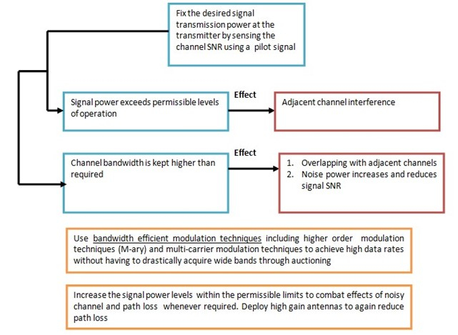
Transmission Power
The transmission power is decided usually based on the distance between the transmitter and receiver. In case of long distance terrestrial communications, repeaters are installed at intermediate stations between the transmitter and receiver. It is a common practice to send a pilot signal across the channel and receive it at a reference receiver. The SNR of this pilot signal is measured to get an idea of how noisy the channel is. If the SNR at the receiver is very poor, then the transmission power is raised without exceeding the permissible levels of operation.
Channel Capacity
To achieve high data rates, the channel bandwidths can’t be increased beyond certain limits. This is because the channel might overlap with adjacent bands thereby causing interference. Without drastically increasing the channel bandwidth, we can adopt effective modulation techniques to step up the data rate of the system. An increase in SNR also increases the wireless channel capacity.
Transmission Bandwidth
An increase in transmission bandwidth also increases the noise power which consequently reduces the SNR. Thus, signal transmission power and channel bandwidth are decided based on the requirements of the application.
$$N_{p}=N_{0}B=kTB$$
Np is the noise power and B is the transmission bandwidth. We can see that there is a linear relation between the transmission bandwidth and the noise power.
Antenna Gain and Path Loss Reduction
In order to reduce the wireless channel path loss, we can deploy high gain antennas. Higher the gain of the antennas at the transmitter and receiver, lower will be the effect of path loss.
According to Friis’s transmission formula, the path loss is given for LOS model, as below in (1)
$$P_{r}=P_{t}G_{t}G_{r}(\frac{\lambda}{4\pi\:d})^{2}\:---(1)$$
Even though this is presented for calculating the power received in a LOS system, this can be applied as an approximate modeling of non-LOS systems too.
Proceeding with the simplification, we have,
$$\frac{P_{t}}{P_{r}}=\frac{1}{G_{t}G_{r}(\frac{\lambda}{4\pi\:d})^{2}}$$
$$PL(dB)=-10log_{10}(G_{t}G_{r})+20log_{10}(\frac{4\pi\:d}{\lambda})---(2)$$
$$PL(dB)=-10log_{10}(G_{t})-10log_{10}(G_{r})+20log_{10}(\frac{4\pi\:d}{\lambda})---(3)$$
From (3), we can observe that if the antenna gains are unity (Gt = Gr = 1), path loss is reduces to
$$PL(dB)=20log_{10}(\frac{4\pi\:d}{\lambda})---(4)$$
However, if we use high antenna gains, the path loss reduces further. This can be observed from (3)
The underlying fact is that prior to establishing a wireless communication link, all possible gains and losses must be taken into consideration in order to avoid unexpected link failures.

387 Views
