
Article Categories
- All Categories
-
 Data Structure
-
 Networking
-
 RDBMS
RDBMS
-
 Operating System
-
 Java
Java
-
 MS Excel
-
 iOS
iOS
-
 HTML
HTML
-
 CSS
CSS
-
 Android
-
 Python
-
 C Programming
-
 C++
C++
-
 C#
C#
-
 MongoDB
-
 MySQL
MySQL
-
 Javascript
-
 PHP
PHP
-
 Economics & Finance
DC Power Supply Filter Types
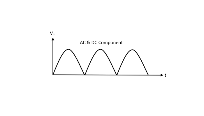
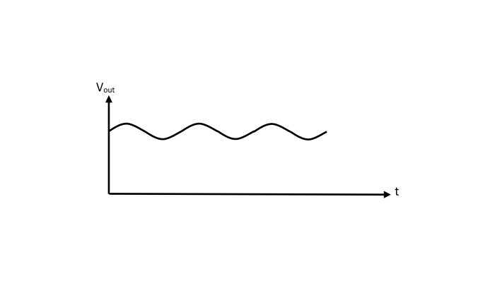
In practice, a rectifier is used to produce pure DC supply in electronic circuits. But the output of a rectifier is not pure DC, it has pulsations, i.e., it contains AC and DC components. The AC component is undesirable and must be removed. For this, a filter circuit is used.
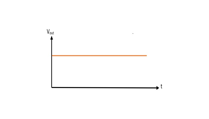
"A Filter Circuit is a circuit which removes the ac component from the output of rectifier and produces the pure dc output across the load."
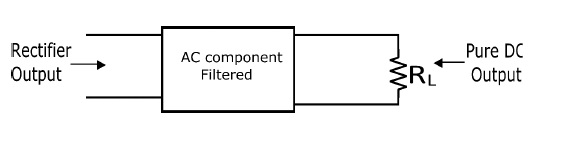
The filter circuit should be placed between the rectifier and the load.
A filter circuit is basically a combination capacitors (C) and inductors (L). A capacitor allows the AC component to pass but does not allow the DC component. On the other hand, an inductor blocks ac component but allows dc component to pass through it.
Types of Filter Circuits
The most common filter circuits are −
- Capacitor filter
- Choke input filter
- Capacitor input or π – filter
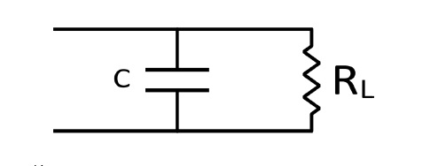
Capacitor Filter
The capacitor filter circuit consists of a capacitor (C) connected in parallel with the load. The pulsating rectified output is applied across the capacitor. The low reactance of the capacitor bypasses the AC component but prevents the DC component to flow through the capacitor. Therefore, only the DC component reaches the load. In this manner, the capacitor filter circuit filtered out the AC component from the output of rectifier and produced the pure dc across the load.

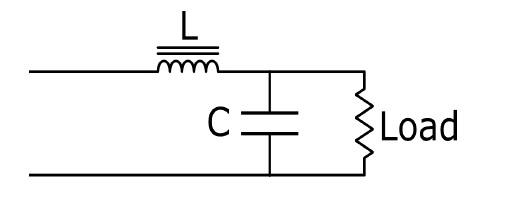
Choke Input Filter
The circuit of choke input filter consists of a choke (inductor) connected in series with rectifier output and a capacitor connected in parallel with the load. The pulsating output of rectifier is applied to the input terminals of the filter circuit. The choke (L) blocks the AC component and allows to pass the DC component. The result is that most of ac component filtered out by the choke and now the remaining ac component bypasses by the capacitor (C) due to its low reactance for the AC component. In this way, only the DC component reaches the load.
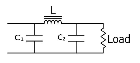
Capacitor Input or π – Filter
The circuit of π–Filter consists of a filter capacitor (C1) connected across the output of rectifier, a choke inductor in series and another filter capacitor (C2) connected across the load. The pulsating rectifier output is applied across the input terminals of the filter circuit. The filtering action of the circuit can be explained as −
Filter Capacitor (C1) − It offers low reactance to the ac component of the output of rectifier, hence it bypasses the ac component and blocks the dc component.
Choke (L) − It blocks the remaining ac component that is not filtered by C1 and allows only dc component to pass through it.
Filter Capacitor (C2) − This capacitor bypasses the ac component which the choke has failed to block. Thus, only dc component reaches the load.

11K+ Views
