 Data Structure
 Networking
 RDBMS
RDBMS Operating System
 Java
Java MS Excel
 iOS
iOS HTML
HTML CSS
CSS Android
 Python
 C Programming
 C++
C++ C#
C# MongoDB
 MySQL
MySQL Javascript
 PHP
PHP
- Selected Reading
- UPSC IAS Exams Notes
- Developer's Best Practices
- Questions and Answers
- Effective Resume Writing
- HR Interview Questions
- Computer Glossary
- Who is Who
Block Diagram of BCD Adder in Computer Architecture?
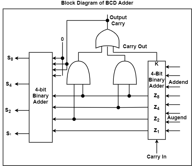
BCD adder refers to a 4-bit binary adder that can add two 4-bit words of BCD format. The output of the addition is a BCD-format 4-bit output word. It can descript the decimal sum of the addend and augend and a carry that is created in case this sum exceeds a decimal value of 9. Therefore, BCD adders can perform decimal addition.
A BCD adder is a circuit that adds two BCD digits in parallel and makes a sum digit also in BCD. A BCD adder should contain the correction logic in its internal construction. To add 0110 to the binary sum, we use a second 4-bit binary adder as shown in the figure.

The two decimal digits, together with the input-carry, are first added in the top 4-bit binary adder to produce the binary sum. When the output-carry is the same as 0, nothing is inserted into the binary sum. When it is the same as 1, binary 0110 is inserted into the binary sum through the bottom 4-bit binary adder. The output-carry created from the lowest binary adder can be rejected because it supplies data already accessible in the output-carry terminal.
A decimal parallel-adder that adds n decimal digits requires n BCD adder phases with the output-carry from one phase linked to the input-carry of the next-higher-order stage. To achieve shorter propagation delays, BCD adders include the necessary circuits for carrying look-ahead. Furthermore, the adder circuit for the correction does not need all four full-adders, and this circuit can be optimized.

