
Article Categories
- All Categories
-
 Data Structure
-
 Networking
-
 RDBMS
RDBMS
-
 Operating System
-
 Java
Java
-
 MS Excel
-
 iOS
iOS
-
 HTML
HTML
-
 CSS
CSS
-
 Android
-
 Python
-
 C Programming
-
 C++
C++
-
 C#
C#
-
 MongoDB
-
 MySQL
MySQL
-
 Javascript
-
 PHP
PHP
-
 Economics & Finance
Band Pass Filter Frequency Response
A band pass filter (BPF) is a circuit that passes frequencies within a certain range and rejects all the frequencies outside the range. This range of band pass filter is known as Bandwidth of the filter.
The Bandwidth of band pass filter is given by,
$$Bandwidth=f_{high}-f_{low}$$
Where, fhigh and flow are the higher and lower cut off frequencies.
The values of fhigh and flow are given by,
$$f_{high}=\frac{1}{2\pi\:R_{2}C_{2}}$$
$$f_{low}=\frac{1}{2\pi\:R_{1}C_{1}}$$
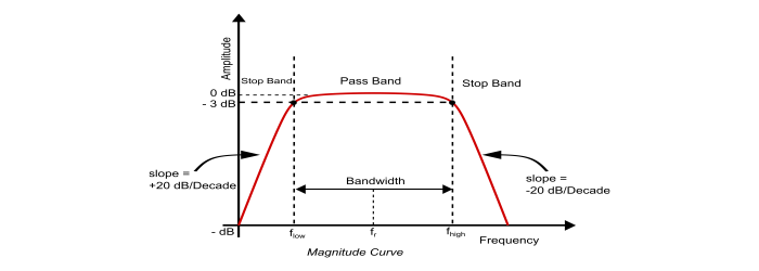
In the frequency response curve or bode plot of the band pass filter, the signal is blocked(attenuated) at low frequencies with the output increasing at the rate of +20dB/Decadeuntil the frequency reaches the Lower Cut off Frequency Point . At the lower cut-off frequency point ( flow ) the amplitude of the output signal is 70.7% of the input signal.
The output increases continuously until it reaches to the Upper Cut off Frequency Point ( fhigh ). From this point the output starts decreasing at a rate of -20dB/Decade and blocking (attenuating) any high frequency signal. The point of maximum output is the geometric mean of the lower cut off frequency ( flow ) and upper cut off frequency ( fhigh ) and is called as the Resonant Frequency or Centre Frequency (fr). The band pass filter is a second–order type filter since it has two energy storing elements in its circuit. Thus, the phase angle will be 180°.
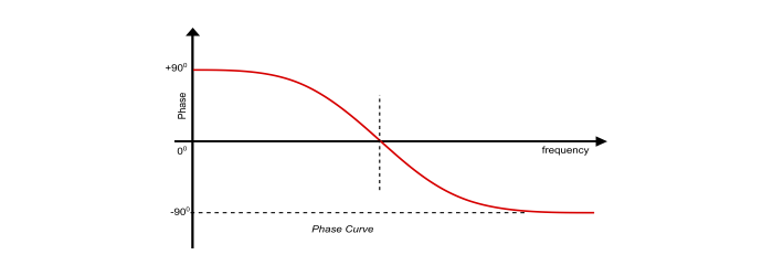
In phase curve, from frequency value 0 to resonant frequency (fr), the output signal leads the input by an angle of 90° . At the resonant frequency, the phase angle becomes zero and then changes to lag the input by 90° as the frequency increases.

6K+ Views
