
Article Categories
- All Categories
-
 Data Structure
-
 Networking
-
 RDBMS
RDBMS
-
 Operating System
-
 Java
Java
-
 MS Excel
-
 iOS
iOS
-
 HTML
HTML
-
 CSS
CSS
-
 Android
-
 Python
-
 C Programming
-
 C++
C++
-
 C#
C#
-
 MongoDB
-
 MySQL
MySQL
-
 Javascript
-
 PHP
PHP
-
 Economics & Finance
Applications of 8212 in mode 0
We use Intel 8212 in variety of applications. Let us discuss applications of 8212 in Mode 0
It acts as buffer which is gated
Bus driver which is Bi-directional
For Interrupting the input port
To supply of eight instructions based on RST.
Intel 8212 as gated buffer: A weak logic signal is converted to a strong logic when 8212 works in logic 0. The outputs of 8212 in mode0 is capable of sinking the 15 mA in 0 state, and which proves that a minimum high output voltage of nearly 3.65 V is in the state 1. Intel8212 is always given backup when the input signal is capable enough to backup 0.25 mA current only. Hence the 8212 when it is in working in the mode 0 it always acts as a buffer.
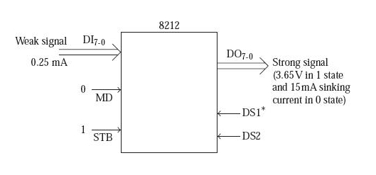
Fig:8212 as a gated buffer
Bi-directional bus driver: Sometimes bidirectional buffering is which is applicable for the data lines of a microprocessor.
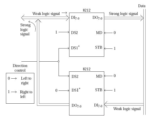
Fig:8212 bi-directional bus driver
We operate both the 8212s in mode 0. The point to be noted they are connected as buffers which are gated. When the direction control is equal to 0, DS1* becomes 0 for the upper 8212, and hence the weak logic signal on the left hand side gets transmitted to the right hand side as a logic signal which is very strong.
Interrupting input port and RSTn interrupt instruction port: The given figure below illustrates the two applications of 8212. The first 8212 which is meant for working is working as an input port performing the interrupt process. It performs data transfer process along with the microprocessor, after interrupting the process. The second 8212 gives the code RSTn to 8085 in response to INTA* from 8085
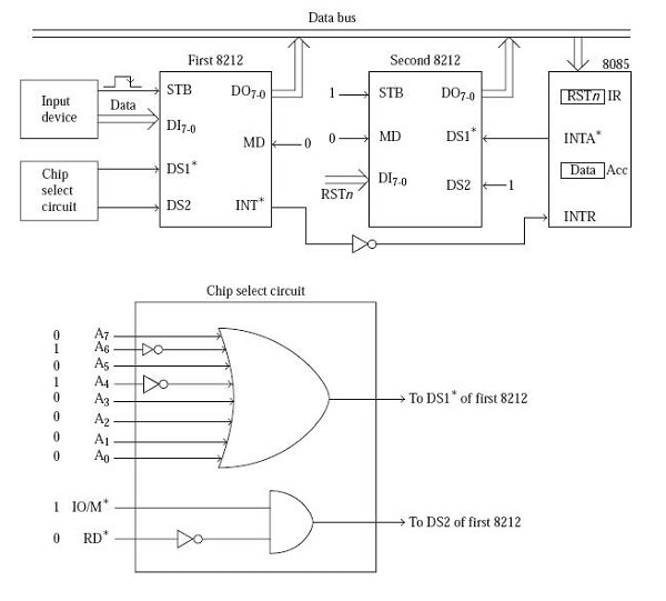
Fig: The interrupting input port and supply port RSTn
Supplier of eight RST instructions: In 8085 we have the TRAP, RST7.5, RST6.5, RST5.5, and INTR as the five pins which are interrupting pins. Let's for example we have Input Output devices which are more than five which would like to perform the interrupt-driven data transfer scheme.
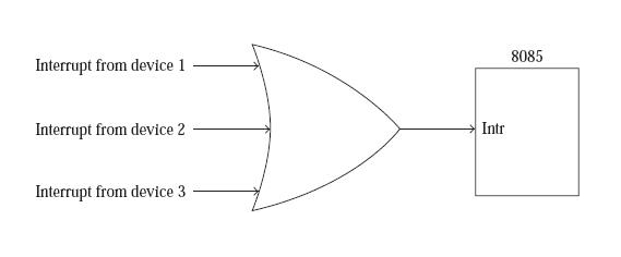
Fig: Several devices interrupting on INTR Pin
We have seen that from the figure, that whenever an interrupt request is generated by the device the output Q of flip-flop D is reset to 0.Initially, all the flip-flop outputs are set to 1 stating the Reset Out signal of 8085.
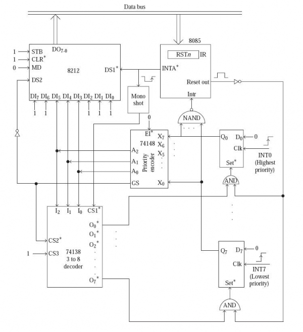
Fig:8212 as supplier of eight RSTn instructions
The output INTA *of 8085 gets connected to the DS1* input of an 8212.
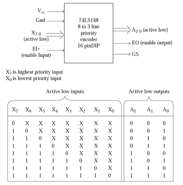
If GS = 0, it means A2, A1, A0 outputs are meaningful.
GS = 0 if EI* = 0 and EO = 1.
EO output will be 1 if at least one of X7 to X0 inputs Is active. i.e.0.
Fig: Truth table of 74148 priority encoder
The point to be noted here that the code for an RST instruction is11nnn111, where nnn may have values from 000 (for RST0) to 111 (forRST7). Thus the data inputs of the 8212 must have the RSTn code depending on the priority of the encoder output.

318 Views
