
Article Categories
- All Categories
-
 Data Structure
-
 Networking
-
 RDBMS
RDBMS
-
 Operating System
-
 Java
Java
-
 MS Excel
-
 iOS
iOS
-
 HTML
HTML
-
 CSS
CSS
-
 Android
-
 Python
-
 C Programming
-
 C++
C++
-
 C#
C#
-
 MongoDB
-
 MySQL
MySQL
-
 Javascript
-
 PHP
PHP
-
 Economics & Finance
Selected Reading
8085 program to perform ON/OFF desired output LEDs connected at the output port B.
Here we will see how to interface PORT IC with 8085.
Problem Statement
ON/OFF desired output LEDs connected at the output port B.
Discussion
Here we will see how to On/Off LEDs at port B. We are using 8255 IC for ports. The J1 and J2 connectors to connect the 8085 and 8255. The connector pin descriptions are given below. For controlling pin, we have to set the control word, that will be used in the program.
|
Pin no. on J1/J2 |
8255 Pin |
Function |
|---|---|---|
|
1 |
13 |
PC4 |
|
2 |
12 |
PC5 |
|
3 |
16 |
PC2 |
|
4 |
17 |
PC3 |
|
5 |
14 |
PC0 |
|
6 |
15 |
PC1 |
|
7 |
24 |
PB6 |
|
8 |
25 |
PB7 |
|
9 |
22 |
PB4 |
|
10 |
23 |
PB5 |
|
11 |
20 |
PB2 |
|
12 |
21 |
PB3 |
|
13 |
18 |
PB0 |
|
14 |
19 |
PB1 |
|
15 |
38 |
PA6 |
|
16 |
37 |
PA7 |
|
17 |
40 |
PA4 |
|
18 |
39 |
PA5 |
|
19 |
2 |
PA2 |
|
20 |
1 |
PA3 |
|
21 |
4 |
PA0 |
|
22 |
3 |
PA1 |
|
23 |
11 |
PC6 |
|
24 |
10 |
PC7 |
|
25 |
26 |
+5V |
|
26 |
7 |
GND |
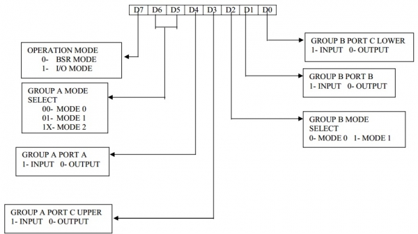
Group A and B will operate in mode 0.
Using port A as input port and port B as output port. The operation mode of port C is immaterial, as it will not be used here. Here the operation mode of port C is considered as input.
Thus setting the control word as (10011001)
Therefore the control word is 99 H.
Program
|
Address |
HEX Codes |
Labels |
Mnemonics |
Comments |
|---|---|---|---|---|
|
8000 |
3E, 99 |
START: |
MVI A, CW |
Load the CW in the accumulator |
|
8002 |
D3, 43 |
|
OUT 43 H |
Output the CW to control register |
|
8004 |
3E, 55 |
|
MVI A, 55 H |
ON alternate output LEDs at port B |
|
8006 |
D3, 41 |
|
OUT 41 H |
Put the pattern byte at output port |
|
8008 |
76 |
|
HLT |
Stop |

Updated on: 2019-07-30T22:30:26+05:30
5K+ Views

Advertisements