 Data Structure
 Networking
 RDBMS
RDBMS Operating System
 Java
Java MS Excel
 iOS
iOS HTML
HTML CSS
CSS Android
 Python
 C Programming
 C++
C++ C#
C# MongoDB
 MySQL
MySQL Javascript
 PHP
PHP
- Selected Reading
- UPSC IAS Exams Notes
- Developer's Best Practices
- Questions and Answers
- Effective Resume Writing
- HR Interview Questions
- Computer Glossary
- Who is Who
What is pass band transmission in Computer networks?
Digital Modulation is the process of converting between bits and signals.
Transmission Mechanisms
The various modulation schemes result in various transmission mechanisms which are as follows −
- Baseband transmission.
- Passband transmission.
Multiplexing Techniques
Sharing of a transmission channel by various signals is called multiplexing. The different multiplexing techniques are as follows −
- Time division multiplexing.
- Frequency division multiplexing.
- Code division multiplexing.
Now, let us discuss one of the digital modulation schemes.
Passband Transmission
Passband transmission is the transmission after shifting the baseband frequencies to some higher frequency range using modulation. It is used for long distances.
Steps for Passband Transmission
Let us understand the Passband transmission step by step.
Step 1 − Generally, we want to use a range of frequencies that does not start at zero to send information across a channel. If you take wireless channels, it is not practical to send very low frequency signals because the size of the antenna needs to be a fraction of the signal wavelength, which becomes too large.
Step 2 − In any case regulatory constraints and the need to avoid interference usually dictate the choice of frequencies. Even for wires, placing a signal in a given frequency band is useful to let different kinds of signals coexist on the channel. This kind of transmission is called passband because an arbitrary band of frequencies is used to pass the signal.
Step 3 − The idea is to take a baseband signal that occupies 0 to B hz and shift it up to occupy a passband of S to S+B hz without changing the amount of information that it can carry, even if the signal looks different.
Step 4 − To process a signal at the receiver, we can shift it back down to baseband. It is more convenient to detect symbols at the receiver.
Step 5 − Digital modulation is accomplished with passband transmission by regulating or modulating a career signal that presents in passband.
Step 6 − It can modulate the amplitude, frequency, or phase of the career signal.
Step 7 − Each of these methods has a corresponding name.
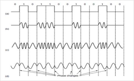
Step 8 − ASK (Amplitude Shift Keying), two different amplitudes are used to represent ‘0’ and ‘1’. More than two levels can be used to represent more levels.
Step 9 − with FSK (Frequency Shift Keying). Two or more different tones are used.
Step 10 − In PSK (Phase Shift Keying), the career wave is systematically shifted 0 or 180 degrees at each symbol period. Because there are two phases called Binary Phase Shift keying.
Step 11 − Binary refers to two symbols, not that the symbol represents 2 bits. A better scheme that uses the channel bandwidth more efficiently is to use four shifts. For example, 45, 136,225 or 315 degrees, are used to transmit 2 bits of information per symbol.
Step 12 − This version is QPSK (Quadrature Phase Shift Keying). Quadrature amplitude modulation (QAM): QAM-16, QAM-64.
Step 13 − In QAM, different combinations of amplitudes and phases are used.
The passband transmission is pictorially represented as follows along with its components −

Here,
(a) − Binary Signal
(b) − Amplitude Shift Keying
(c) − Frequency Shift keying
(d) − Phase Shift keying.

