
Article Categories
- All Categories
-
 Data Structure
-
 Networking
-
 RDBMS
RDBMS
-
 Operating System
-
 Java
Java
-
 MS Excel
-
 iOS
iOS
-
 HTML
HTML
-
 CSS
CSS
-
 Android
-
 Python
-
 C Programming
-
 C++
C++
-
 C#
C#
-
 MongoDB
-
 MySQL
MySQL
-
 Javascript
-
 PHP
PHP
-
 Economics & Finance
What is a Yagi-uda antenna? What are its design specifications?
Yagi-Uda antenna is the most commonly used type of antenna for TV reception over the last few decades. It is the most popular and easy-to-use type of antenna with better performance, which is famous for its high gain and directivity. The frequency range in which the Yagi-Uda antennas operate is around 30 MHz to 3 GHz which belong to the VHF and UHF bands.
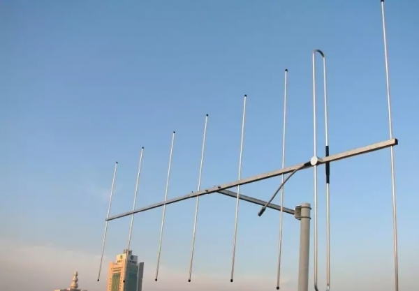
Construction of Yagi-Uda Antenna
A Yagi-Uda antenna was seen on top of almost every house during the 90's when we had only Doordarshan Channels. The parasitic elements and the dipole together form this Yagi-Uda antenna. It is seen that there are many directors placed to increase the directivity of the antenna.
The feeder is the folded dipole. The reflector is the lengthy element, which is at the end of the structure. The following figure depicts the parts of the Yagi-Uda antenna.
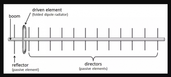
The center rod-like structure on which the elements are mounted is called as a Boom. The element to which a thick black head is connected is the driven element to which the transmission line is connected internally, through that black stud.
The single element present at the back of the driven element is the reflector, which reflects all the energy towards the direction of the radiation pattern. The other elements, before the driven element, are the directors, which direct the beam towards the desired angle.
Designing
For this antenna to be designed, the following design specifications should be followed. If the specifications given above are followed, one can design a Yagi-Uda antenna.
| ELEMENT | SPECIFICATION |
|---|---|
| Length of the Driven Element | 0.458λ to 0.5λ |
| Length of the Reflector | 0.55λ to 0.58λ |
| Length of the Director 1 | 0.45λ |
| Length of the Director 2 | 0.40λ |
| Length of the Director 3 | 0.35λ |
| Spacing between Directors | 0.2λ |
| Reflector to dipole spacing | 0.35λ |
| Dipole to Director spacing | 0.125λ |
If the specifications given above are followed, one can design a Yagi-Uda antenna.

788 Views
