- Cellular Concepts - Introduction
- GSM Architecture
- Cellular Concepts - GSM Radio Link
- Cellular Concepts - Mobility
- Cellular Concepts - GPRS
- Cellular Concepts - EDGE
- UMTS Introduction
- UMTS - A New Network
- UMTS - WCDMA Technology
- UMTS - HSPA Standardization
- UMTS - Objectives
- UMTS - Authentication
- UMTS - Success and Limitations
- UMTS Networks Standardization
- UMTS - 3GPP
- UMTS - Radio Access Network
- UMTS - Evolved Packet Core
- UMTS Protocol Environment
- UMTS - GPRS Tunneling Protocol
- UMTS - Proxy Mobile IPv6
- UMTS - EAP
- UMTS - IKEv2 & MOBIKE
- UMTS - SCTP
- UMTS - NAS Signaling Protocol
- UMTS Useful Resources
- UMTS - Quick Guide
- UMTS - Useful Resources
- UMTS - Discussion
UMTS - Protocol Environment
The generation of GPRS Tunneling Protocol (GTP) was virtually impossible, but is also not desirable to give it for the new system, but, on the other hand, it is quite understandable that the improvements are also needed in order to be able to interact with the world of legacy PS smoothly and support functions needed for the newest system.
GPRS Tunneling Protocol (GTP)
GTP protocol is designed for tunneling and encapsulation of data units and control messages in GPRS. Since its design in the late 1990s, it was put to deploy on a large scale, and solid experience has been gathered.
GTP for Evolved 3GPP system is available in two variants, control and user plane. GTP-C manages the control plane signaling, and it is necessary in addition to the data transfer protocol on the purity of the user, GTP-U; it is called user plane. Current versions, suitable for EPS are GTPv1 US and GTPv2-C.
The peculiarity of GTP is that it supports the separation of traffic within its primary GTP tunnel holder, or in other words, the ability to group them together and treat carriers. The ends of GTP tunnels are identified by TEIDs (Tunnel Endpoint identifiers); they are assigned to the local level for the uplink and downlink by peer entities and reported transversely between them. TEIDs are used on different granularity by specific example PDN connection on S5 and S8 and EU on S3 / S4 / S10 / S11 interfaces.
Control Plane of GPRS Tunneling Protocol
GTPv2-C is used on the EPC signaling interfaces (including SGSNs of at least Rel. 8). For example −
- S3 (between SGSN and MME),
- S4 (between SGSN and Serving GW),
- S5 and S8 (between Serving GW and PDN GW),
- S10 (between two MMEs), and
- S11 (between MME and Serving GW).
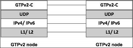
Corresponding to this, a typical GTPv2-C protocol data unit like shown in the figure above, the specific part GTP is preceded by IP and UDP headers, it consists of a header GTPv2-C and part containing information GTPv2-C variable in number, length and format, depending on the type of the message. As the echo and the notification of a protocol version is not supported, TEID information is not present. The version is obviously firmly set at 2 in this version of the protocol.
GTP had a complex legacy extension header mechanism; it is not used in most GTPv2-C. The message type is defined in the second byte (so the maximum of 256 messages can be defined for future extensions). Below table provides an overview of messages currently defined GTPv2-C. The length of the message is coded in bytes 3 and 4 (measured in bytes and not containing the first four bytes themselves).
TEID is the ID of the tunnel end point, a single value on the opposite/receiving side; it allows multiplexing and de-multiplexing tunnels at one end in the very frequent cases over a GTP tunnel must be distinguished.
| Message Type | Message | Additional Explanation |
|---|---|---|
| 0 | Reserved | Shall never be used (intentionally excluded from protocol, to enforce explicit setting) |
| 1/2 | Echo Request/ Response | Used to probe if a GTP version supported by the sending node. |
| 3 | Version Not Supported Indication | Contains the latest GTP version supported the sending node. |
| 4/5 | Direct Transfer Request/ Response | Used for tunneling signaling message on S101 interface for optimized handover, between HRPD access not and MME |
| 6/7 | Notification Request/ Response | Used for tunneling notification on S101 between HRPD access node and MME |
| 25/26 | SRVCC PS to CS request | Used to trigger and confirm SRVCC initiation between SGSN/MME and MSC server |
| 27/28 | SRVCC PS to CS complete Notification | Used to indicated and confirm completion of SRVCC between MSC server and SGSN/ MME |
| 32/33 | Create Session Request | Used to establish connectivity between two nodes |
| 34/35 | Modify Bearer Request | Used to modify properties of a single or of multiple bearer, include bearer context information |
| 36/37 | Delete Session Request | Tears down GTP control session |
| 38/39 | Change Notification request | Used for reporting location information |
| 66/67 | Delete bearer command/ failure indication | Instruct nodes to delete bearer and confirm back |
| 68/69 | Bearer resource command/ failure indication | Used to allocate or modify resources |
| 73 | Stop paging indication | Sent from SGW to the MME or SGSN |
| 95/96 | Create bearer request/ response | Instruct nodes to install bearers and confirms back |
| 97/98 | Update bearer request | Used to inform the control plane nodes from the user plane about bearer changes |
Enhanced GTPv1-U
Only a small but effective improvement was applied to GTP-U, and for that it was not considered necessary to strengthen the number of protocol version. Thus, we still expect GTPv1-U, but at least its most recent Rel. 8.
The protocol stack is essentially the same as for GTPv2-C with only the name of the layers and the protocols substituted accordingly. The extension header mechanism is kept in place; it allows inserting two elements if necessary.
UDP source port of the triggering message (two octets);
PDCP PDU number − related to the characteristic transfer without loss; in this case, data packets need to be numbered in the EPC (two octets).
The improvement is the ability to transmit an "end market" in the user plane. It is used in the inter-eNodeB handover procedure and gives the indication that the pathway is activated immediately after the data packet, for example, the feature is not necessary to pre-Rel.8 because GTP-U did not end in the radio access node (i.e. not in the BS or NodeB) only a few messages exist. GTPv1-U, and they are listed in the table above.
It is clear that, in fact a very limited kind of signaling is possible via GTPv1-U (echo mechanisms and end labeling). The only message that the transfer of real user data is of type 255, the so-called G-PDU message; the only piece of information it carries, after the header is the original data packet from a user or external PDN equipment.
Not all instances of GTP-U tunnels are listed in the reference architecture (which aimed to capture the associations were no longer living between network nodes); temporary tunnels are possible −
Between two Serving GWs, applicable for the transfer based on S1, in the case that the service is moved GW;
Between two SGSNs, corresponds to the previous case, but in the legacy PS network;
Between two RNCs, applicable for the relocation of the RNC in the 3G PS network (no relation to the EPC, it is mentioned here just for completeness).
Proxy Mobile IPv6 (PMIPv6) Protocol
It is a mobility management protocol standardized by Internet Engineering Task Force (IETF) which works on developing internet protocol standards.
Dual Stack Capability
Dual stack capability for PMIPv6 has two targets −
To support IPv4 home addresses
To allow IPv4 only transport across the access network; in this case the MAG may use also an IPv4 private address, and a NAT may be deployed along the path towards the LMA.
These two features can be used independently. To solve these requirements, the following extensions made −
In the Binding Cache of LMA −
IPv4 address assigned to the mobile node and now registered with the mobile access gateway (including corresponding subnet mask). It comes either from static configuration/profile or is dynamically allocated by LMA.
IPv4 default-router address assigned to the mobile node.
In the Binding Update list of MAG −
IPv4 home address assigned to the mobile attached interface.
IPv4 default router of the mobile node. The LMA and MAG should implement IPv6, and they also need an IPv4 address. MAG is the IPv4 Default Router for the UE on its access link.
PMIPv6 Signaling
Table below provides an overview of PMIPv6 signaling messages (basic PMIPv6 and specified improvements in IETF for connecting dismissal and way of management). Signaling PMIPv6 base is made with "Binding Update" (BU) MAG to LMA, and a corresponding "Update acknowledgment Binding" (BUA) messages back to MAG is used for registering, refreshing and binding deletion. IP address information (IPv4 or IPv6 address prefix) is usually requested by the LMA and MAG assigned by the initial enrollment.
| PMIPv6 Signaling Message | Direction | Description | |
|---|---|---|---|
| Binding Update | PBU | MAG -> LMA | Requests creations, extension and deletion of a mobility binding. It is also used to request a new IPv4 address. |
| Binding Update Acknowledgement | PBA | LMA -> MAG | Acknowledges the requests for creation, extension and deletion of a mobility binding. It is also used to allocate and IPv4 address. |
| Binding Revocation Indication | BRI | LAM -> MAG | Notification that a binding is revoked and thus will be deleted by LAM, allows also bulk revocations. |
| Binding Revocation Acknowledgement | BRA | MAG -> LMA | Acknowledges a binding revocation. |
| Heartbeat | HB |
MAG -> LMA LMA -> MAG |
Periodic signaling message, used for detecting failure. |
3GPP Specific Information Elements Added to PMIPv6
PMIPv6 is designed for a very general use; 3GPP has some special requirements arising from the need to make it compatible as possible with capacities of GTP.
| Vendor Specific Information | Direction | Explanation |
|---|---|---|
| Protocol Configuration | MAG->LMA | Mirrored from GTP, used to transfer frequently needed, protocol related data |
| Options | LMA->MAG | between UE and network. |
| Specific 3GPP related error code | LMA->MAG | It can indicate that no access is given to an APN. |
| Connection Set Identifier (CSI) |
LMA->MAG MAG->LMA |
Contains one or more CSIs. It is generated for each new PDN connection and used in case of partial node failure to identify the PDN. |
| PDN type indication | LMA->MAG | Used to indicate the decision of the PDN GW. |
| PDN GW IP address | MAG->LMA | Used in case of chaining on S2a/S2b to transfer to the intermediate LMA. |
| DHCPv4 address allocation indication | LMA->MAG | Indicates that IP at allocation through DHCPv4 is to be used by the UE. |
Extensible Authentication Protocol (EAP)
It is a generic framework developed by the IETF (RFC 3748). The basic signaling mechanism supports different authentication methods on top.
The EAP specific use for interworking with a 3GPP system is defined by the EAP-AKA method EAP-AKA is already used in I-WLAN.
The principal steps for EAP authentication are given below −
EAP authenticator sends an authentication request to the target device/EU (L2); it receives the response from the target device/EU and transmits it to the AAA infrastructure.
AAA server performs the EAP method, resulting in a challenge to the target device, which is sent by the authenticator.
The target device must meet the challenge; the answer is relayed to the AAA server via the authenticator.
AAA server compares the response to challenge with that expected and decides to successful authentication. An indication of success or failure is returned to the target device.
Optionally, the notifications can be used to transfer additional information; this is used for the IP mobility mode selection indication. During the design there was a major decision to separate areas of the safety of non-3GPP access networks in the field of security 3GPP, and also to the other domain.
The practical consequence is that the identifier of non 3GPP access network enters the security algorithm, which requires the specification of a variant of EAP-AKA, EAP-AKA (premium).
Internet Key Exchange Protocol Version 2 (IKEv2) and MOBIKE
Internet Key Exchange is a sophisticated version 2 defined by the IETF in RFC 4306. It allows creating and maintaining security associations and IPSec tunnels between two nodes and exchanging some configuration data; they are transferred to the so-called payload configuration dialogues in the message.
Comprehensive IKEv2 session consists of multiple dialogues, structured phases. The flow of messages and typical base is given in the figure below, and a description of how it is applied in the context of signaling between EU and ePDG −
| IKEv2Phase | Comments |
|---|---|
| Initial Exchange |
Notifies payload as MOBIKE support indication. IP address to be requested/ delivered in configuration payload. Home agent address to be requested/ provided in configuration payload. |
| Auth Exchange | |
| Create child SA | For creating protected tunnel for DSM IPv6 signaling |
| x. Information Exchange | At any point after AUTH. |
In the Evolved 3GPP system IKEv2 is used for −
- IP address information: either IPv4 address or IPv6 prefix.
- IP mobility mode selection information.
- IP address information: IPv6 prefix.
- DNS server address.
Diameter
The diameter is a generic AAA protocol, with additional functions for network access, mobility and QoS handling. Although it is in principle, of a general nature peer-to-peer, it is used in the 3GPP architecture in the client-server mode. It has a built-in extensibility and so perfectly supports message structures on the interfaces with the need for some flexibility. In addition, it supports multiple server configurations with failure and failover handling. Functionally, it has similarities with its predecessor radius but differs profoundly on the level of message and parameters. DIAMETER offers ability to detect a dead peer by pairs of heartbeat messages. It can be run over SCTP or TCP and uses the 3868 port.
The DIAMETER protocol is used extensively in the EPC −
S6a for subscription download and update between MME and HSS.
S6d (between an upgraded SGSN and HSS), which is the counterpart of S6a for the legacy world with interworking capability with the new system.
S13 for equipment checking between MME and EIR.
SWa for authentication between untrusted non-3GPP access and AAA server.
STa for authentication between trusted non-3GPP access and AAA server and authorization.
SWd for forwarding between an AAA proxy and a AAA server (forwarding between VPLMN and HPLMN).
S6b for authorization of APN and mobility between PDN GW and AAA server.
SWm for authentication and authorization between ePDG and AAA server.
SWx for exchange of authentication vector and registration information between AAA server and HSS.
Gx for IP-CAN session handling and GW-Control Session handling between PDN GW and PCRF.
Stream Control Transmission Protocol (SCTP)
SCTP is a reliable transport protocol that runs on top of a packet service without potentially unreliable connection such as IP. It was developed specifically for applications and signaling offers recognized without unduplicated transfer error datagrams (messages). Detection of data corruption, data loss and data duplication is performed using checksums and sequence numbers.
A selective retransmission mechanism is applied to correct the loss or corruption of data. The decisive difference is TCP multi-homing and the concept of multiple streams in a connection. Where in a TCP flow is called a sequence of bytes, a SCTP stream represents a sequence of messages. SCTP tries to combine the advantages of UDP and TCP, but avoid their drawbacks; it is defined in IETF RFC 4960.
SCTP is used on several network internal control plane interfaces, with these SCTP applications −
- S1-MME: between eNodeB and MME
- SBc: between MME and SBc.
- S6a: between MME and HSS
- S6d: between SGSN and HSS
- SGs: between MSC/VLR and MME
- S13: between MME and EIR
S1 Application Protocol
Two categories of procedures across S1-MME exist: UE associated and non-associated UE. Furthermore two classes of messages are defined: Class1 is with the class 2 is answered. Class 1 and related procedures initiator/response messages are listed in the table below; procedures for Class 2 message names are largely identical to the procedure names, and the table below (second table) lists only these.
| Elementary Procedure | Initiating Message | Response(if successful) |
|---|---|---|
| Handover preparation | Handover required | Handover command |
| Hand resource allocation | Handover req. | Path switch req. ack. |
| Patch Switch Request | Path Switch Req. | Path switch ack. |
| Handover Cancellation | Handover cancel | Handover cancel ack. |
| E-RAB Setup | E-RAB setup Req. | E-RAB setup Resp. |
| E-RAB modify | E-RAB modify req. | E-RAB modify Resp. |
| E-RAB release | E-RAB command release | E-RAB command Resp. |
| Initial context setup | Initial context setup req. | Initial context setup Resp. |
| Reset | Reset | Reset Ack. |
| S1 setup | S1 setup req. | S1 setup Resp. |
| UE context release | UE context release command | UE context release complete |
| UE context modification | UE context modification req. | UE context modification resp. |
| eNodeB configuration | ENB configuration update | ENB configuration update ack. |
| MME Configuration | MME configuration update | MME configuration update ack. |
| Write- Replace warning | Write-Replace warning req. | Write-Replace warning resp. |
Elementary Procedure
- Handover Notification
- E-RAB release indication
- Paging
- Initial UE message
- Downlink NAS transport
- Uplink NAS transport
- NAS non delivery indication
- Deactivate Trace
- Trace start
- Trace failure indication
- Location reporting failure indication
- Location reporting control
- Location report
- Cell Traffic Trace
- Error indication
- UE Context release request
- Downlink S1 CDMA2000 tunneling
- uplink S1 CDMA2000 tunneling
- UE capability info indication
- eNodeB status transfer
- MME status transfer
- Overload Start
- Overload Stop
- eNodeB direct information Transfer
- MME direct information transfer
- eNodeB configuration transfer
- MME configuration
X2 Application Protocol
X2 application protocol has much in common with the S1-AP; same categorization in class 1 and class 2 messages is made. The setup message is much smaller, corresponding to the specialized function of X2.
| Procedure | Initiating Message | Class | Response(if successful) |
|---|---|---|---|
| Handover preparation | Handover req. | 1 | Handover req. ack. |
| Reset | Reset req. | 1 | Reset resp. |
| X2 setup | X2 setup | 1 | X2 setup resp. |
| eNodeB Configuration update | ENB Configuration update | 1 | ENB Configuration update ack. |
| Resource Status Reporting Initiation | Resource Status req. | 1 | Resource Status resp. |
| Load Indication | Load Information | 2 | |
| Handover Cancel | Handover Cancel | 2 | |
| SN status transfer | SN status transfer | 2 | |
| UE context release | UE context release | 2 | |
| Resource Status | Resource Status | 2 | |
| Reporting | update | ||
| Error Indication | Error Indication | 2 |
NAS Signaling Protocol
The NAS signaling protocol is genuinely a 3GPP protocol and developed for 3GPP only, hence, nowhere else than in 3GPP systems this protocol could be found.
- UE for mobility and session management.
- MME for EPC and legacy network nodes (SGSN for GPRS and MSC for CS domain).
- Messages exchanged.
NAS Signaling Protocol for EPS Mobility Management
NAS signaling EPS mobility management procedures are listed in below table. The "X" in the column "C" indicates whether a variant on the combination with the CS NAS signaling protocol stack is on matching (the case for a configuration with CSFB allowed, under the purported combined).
Only cases of success were presented (if an error occurred using appropriate rejection messages, mainly through the network); the explanation does not include all possible cases. The dialogues messages are usually kept by timers against loss of messages; e.g. timer T3410 is used to supervise the procedure and attach expires after 15 seconds. So if no response (acceptance or rejection) from the network, a retry procedure is started. Counters are used to limit retries. Mobility EPS Management network operates seven timers and timers UE 14.
| Procedure | Messages | Explanation |
|---|---|---|
| GUTI reallocation | GUTI reallocation command ← | Used to allocate a temporary identifier to the UE. |
| GUTI reallocation Complete → | ||
| Authentication | Authentication req.← | Used to authenticate the UE. |
| Authentication resp.→ | ||
| Security mode control | Security mode command← | Used to negotiate between UE and MME. |
| Security mode command→ | ||
| Identification | Identity req.← | Used to determine a UEs identity. |
| Identity resp.→ | ||
| EMM information | EMM information ← | Used to transfer support information to UE. |
| EMM Status | EMM status ← or → | Used for error reporting. |
| Attach | Attach req.← | Used to register the UE with the network and allocation of the resources. |
| Attach accept← | ||
| Attach Complete→ | ||
| Detach | Detach req.→ | Used to remove a UEs registration with the network. |
| Detach accept ← or → | ||
| Tracking area updating | Tracking area update req.→ | Used for idle mode mobility. |
| Tracking area update accept ← | ||
| Service Request | Service req. → | Used when the UE is in idle mode. |
| Paging | Request to lower layer for paging | Used when UE is in idle mode and downlink traffic arrives. |
| Service req. | ||
| Transport of NAS message | UL/DL NAS transport ← / → | Used for SMS transport in encapsulated form. |
NAS Signaling Protocol for EPS Session Management
The second block of the NAS signaling functionality is related to the handling of the session. Four insider network and four UE has initiated the procedures that exist in ESM. Following table lists the messages with the corresponding flows for the success (again, negative cases are created using appropriate reject messages). Some of them are grafted on EMM NAS messages, where a container is provided (for example a REQUEST PDN connectivity is packed on the attach request message). Also two simple messages have been defined for general information exchange.
| Procedure | Messages | Explanation |
|---|---|---|
| Default EPS bearer context activation | Activate default EPS bearer context req. ← | Establishes a default EPS bearer context between UE and EPC. |
| Activate default EPS bearer context req. → | ||
| Dedicated EPS bearer context activation | bearer context req.← | context with QoS and TFT between UE and EPC. |
| Activate dedicated EPS bearer context req.→ | ||
| EPS bearer context Modification | Modification EPS bearer context req. ← | Modifies an existing EPS bearer context for QoS and TFT between UE and EPC. |
| Modification EPS bearer context accept. ← | ||
| EPS bearer context deactivation | Deactivation EPS bearer context req. ← | Deactivate an EPS bearer context. |
| Deactivation EPS bearer context accept. ← | ||
| UE requested PDN connectivity | PDN connectivity req. → | Requests setup of a default bearer to a PDN. |
| PDN connectivity accept ← | ||
| UE requested PDN disconnect | PDN disconnect req. → | Disconnect UE from one PDN. |
| Deactivation EPS bearer context req. ← | ||
| UE requested bearer resources allocation | Bearer resource allocation. → | Used to request bearer resources. |
| Modify EPS bearer context req. ← | ||
| UE requested bearer resource modification | Bearer resource modification req. → | Used to modify. |
| Modify EPS bearer context req. ← | ||
| ESM information request | ESM information request ← | Used to request protocol configuration option. |
| ESM information response → | ||
| ESM status | ESM status ← or → | Informs to other NAS signaling peer of errors. |