
Article Categories
- All Categories
-
 Data Structure
-
 Networking
-
 RDBMS
RDBMS
-
 Operating System
-
 Java
Java
-
 MS Excel
-
 iOS
iOS
-
 HTML
HTML
-
 CSS
CSS
-
 Android
-
 Python
-
 C Programming
-
 C++
C++
-
 C#
C#
-
 MongoDB
-
 MySQL
MySQL
-
 Javascript
-
 PHP
PHP
-
 Economics & Finance
Timers of 8051
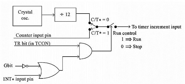
In Intel 8051, there are two 16-bit timer registers. These registers are known as Timer0 andTimer1. The timer registers can be used in two modes. These modes areTimer mode and the Counter mode. The only difference between these two modes is the source for incrementing the timer registers.
Timer Mode
In the timer mode, the internal machine cycles are counted. So this register is incremented in each machine cycle. So when the clock frequency is 12MHz, then the timer register is incremented in each millisecond. In this mode it ignores the external timer input pin.
Counter Mode
In the counter mode, the external events are counted. In this mode, the timer register is incremented for each 1 to 0 transition of the external input pin. This type of transitions is treated as events. The external input pins are sampled once in each machine cycle, and to determine the 1or 0 transitions, another machine cycle will be needed. So in this mode, at least two machine cycles are needed. When the frequency is12MHz, then the maximum count frequency will be 12MHz/24 = 500KHz. So for event counting the time duration is 2 µs.
There are four different modes of the Timer or Counter. The Mode 0 to Mode 2 are for both of the Timer/Counter. Mode 3 has a different meaning for each timer register. There is a register called TMOD. This register can be programmed to configure these timers or counters.
The Serial port is used for serial communication in mode 1 and 3. Timer1 is used for generating the baud rate. So only Timer0 is available for timer or counter operations.
TMOD Register
TMOD(Timer Mode) is an SFR. The address of this register is 89H. This is not bit-addressable.
| Timer |
Timer1 Mode |
Timer0 Mode |
||||||
|---|---|---|---|---|---|---|---|---|
| Bit Details |
Gate (G) |
C/T |
M1 |
M0 |
Gate (G) |
C/T |
M1 |
M0 |
Now, let us see the circuit that controls the running of the timers.
In the following table, we will see the bit details and their different operations for high or low value.
| Bit Details |
High Value(1) |
Low Value(0) |
|---|---|---|
| C/T |
Configure for the Counter operations |
Configure for the Timer operations |
| Gate (G) |
Timer0 or Timer1 will be in RunMode when TRX bit of TCON register is high. |
Timer0 or Timer1 will be in RunMode when TRX bit of TCON register is high and INT0 or INT1 is high. |
|
Bit Details |
00 |
01 |
10 |
11 |
|---|---|---|---|---|
| M1 M0 |
This is for Mode 0. (8-bit timer/counter, with 5-bit pre-scaler) |
This is Mode 1. (16-bit timer/counter) |
This is Mode 3 (8-bit auto reload-timer/counter) |
This is Mode 3 (The function depends on Timer0 or Timer1) |
The Gate bit will be high when the timer or counter is in mode 0 to 2.
Examples
To configure the Timer0 as 16-bit event counter and Timer1 as 8-bit auto reload counter, we can use the bit pattern 0 0 1 0 0 1 0 1. It is equivalent to 25H. If we want to program the TMOD register with this bit pattern, we can use this instruction:
MOVTMOD, #25H
The above instruction is executed, then the timer/counter will be controlled by the software. To configure the system as hardware controlled mode, then the gate bits will be 1. So the bit patterns will be 1 0 1 0 1 1 0 1 = ADH
we can use this instruction:
MOVTMOD, #0ADH
Mode 0 of Timer/Counter
The Mode 0 operation is the 8-bit timer or counter with a 5-bit pre-scaler. So it is a 13-bit timer/counter. It uses 5 bits of TL0 or TL1 and all of the 8-bits of TH0 or TH1.
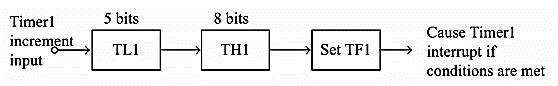
In this example the Timer1is selected, in this case, every 32 (25)event for counter operations or 32 machine cycles for timer operation, the TH1 register will be incremented by 1. When the TH1overflows from FFH to 00H, then the TF1 of TCON register will be high, and it stops the timer/counter. So for an example, we can say that if the TH1 is holding F0H, and it is in timer mode, then TF1will be high after 10H * 32 = 512 machine cycles.
MOVTMOD, #00H
MOVTH1, #0F0H
MOVIE, #88H
SETB TR1
In the above program, the Timer1 is configured as timer mode 0. In this case Gate = 0. Then the TH1 will be loaded with F0H, then enable the Timer1 interrupt. At last set the TR1 of TCON register, and start the timer.
Mode 1 of Timer/Counter
The Mode 1 operation is the 16-bit timer or counter. In the following diagram, we are using Mode 1 for Timer0.
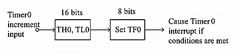
In this case every event for counter operations or machine cycles for timer operation, the TH0– TL0 register-pair will be incremented by 1. When the register pair overflows from FFFFH to 0000H, then the TF0 of TCON register will be high, and it stops the timer/counter. So for an example, we can say that if the TH0 – TL0 register pair is holding FFF0H, and it is in timer mode, then TF0 will be high after 10H = 16 machine cycles. When the clock frequency is 12MHz, then the following instructions generate an interrupt 16 µs after Timer0 starts running.
MOVTMOD, #01H
MOVTL0, #0F0H
MOVTH0, #0FFH
MOVIE, #82H
SETB TR0
In the above program, the Timer0 is configured as timer mode 1. In this case Gate = 0. Then the TL0 will be loaded with F0H and TH0 is loaded with FFH, then enable the Timer0 interrupt. At last set the TR0 of TCON register, and start the timer.
Mode 2 ofTimer/Counter
The Mode 2 operation is the 8-bit auto reload timer or counter. In the following diagram, we are using Mode 2 for Timer1.
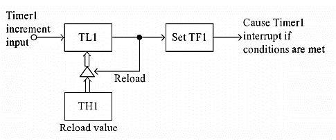
In this case every event for counter operations or machine cycles for timer operation, the TL1register will be incremented by 1. When the register pair overflows from FFH to 00H, then the TF1 of TCON register will be high, also theTL1 will be reloaded with the content of TH1 and starts the operation again.
So for an example, we can say that if the TH1 and TL1 register both are holding F0H and it is in timer mode, then TF1 will be high after 10H= 16 machine cycles. When the clock frequency is 12MHz this happens after 16 µs, then the following instructions generate an interrupt once every 16 µs after Timer1 starts running.
MOVTMOD, #20H
MOVTL1, #0F0H
MOVTH1, #0F0H
MOVIE, #88H
SETBTR1
In the above program, the Timer1 is configured as timer mode 2. In this case Gate = 0. Then the TL1 and TH1 are loaded with F0H. then enable the Timer1 interrupt. At last set the TR1 of TCON register, and start the timer.
Timer1 in mode 2 generates the desired baud rate when the serial port is working on Mode 1 or 3.
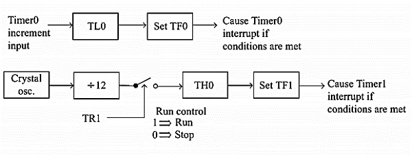
Mode 3 of Timer/Counter
Mode 3 is different for Timer0 and Timer1. When the Timer0 is working in mode 3, the TL0 will be used as an 8-bit timer/counter. It will be controlled by the standard Timer0 control bits, T0 and INT0 inputs. The TH0 is used as an 8-bit timer but not the counter. This is controlled by Timer1 Control bit TR1. When the TH0 overflows from FFH to 00H, then TF1 is set to 1. In the following diagram, we can Timer0 in Mode 3.
When the Timer1 is working in Mode 3, it simply holds the count but does not run. When Timer0 is in mode 3, the Timer1 is configured in one of the mode 0, 1 and 2. In this case, the Timer1 cannot interrupt the microcontroller. When the TF1 is used by TH0 timer, the Timer1 is used as Baud Rate Generator.
The meaning of gate bit in Timer0 and Timer1 for mode 3 is as follows
It controls the running of 8-bit timer/counter TL0 as like Mode 0, 1, or 2. The running of TH0 is controlled by TR1 bit only. So the gate bit in this mode for Timer0 has no specific role.
The mode 3 is present for applications requiring an extra 8-bit timer/counter. In Mode 3 of Timer0, the 8051 has three timers. One 8-bit timer by TH0, another8-bit timer/counter by TL0, and one 16-bit timer/counter by Timer1.
If the Timer0 is in mode3, and Timer1 is working on either 0, 1 or 2, then the gun control of the Timer1 is activated when the gate bit is low or INT1 is high. The run control is deactivated when the gate is high and INT1 is low.

86K+ Views
