 Data Structure
 Networking
 RDBMS
RDBMS Operating System
 Java
Java MS Excel
 iOS
iOS HTML
HTML CSS
CSS Android
 Python
 C Programming
 C++
C++ C#
C# MongoDB
 MySQL
MySQL Javascript
 PHP
PHP
- Selected Reading
- UPSC IAS Exams Notes
- Developer's Best Practices
- Questions and Answers
- Effective Resume Writing
- HR Interview Questions
- Computer Glossary
- Who is Who
The First IOT Program
To start learning IoT, first, it is important to learn how to make circuits using a breadboard and a microcontroller. Then it is important to control that circuit using a program. There are some simulators available to make the beginner of IOT learn both these concepts without even having the IOT devices available. However, to get real results, using the circuit components and making the actual circuit is important. In this article, using two different examples, the way to start IOT programming is given. In example 1, the Wokwi simulator is used and in example 2, the actual circuit using a breadboard, ESP32, LEDs, resistors, and wires are made and the components are controlled using the C program made using the Arduino IDE.
Example 1: Getting started using Wokwi and the first IOT program in C
Wokwi is an online place where virtual circuits can be made and programs to control these circuits can be written and then the results can be tested. It is an easy to use and free service to start with learning IOT. The wokwi link is given here.
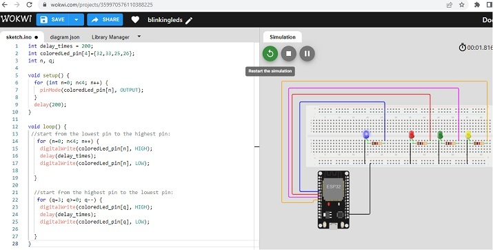
After login into wokwi, first, make the circuit in the right side area and write the code using C language in the left side code area as shown in the fig no.1
Circuit Design Steps and Coding
Step 1 ? Log in to Wokwi. Start a new ESP32 project on Wokwi Simulator.
Step 2 ? Put a breadboard with ESP32 on the virtual circuit area using the + sign.
Step 3 ? Attach the breadboard negative rail to the ESP32's GND.
Step 4 ? Use four LEDS. Connect the smaller legs of LEDs to blue rail and the other lines to resistors. Now connect the resistors to ESP32 pins (D32, D33, D25, D26 )
Step 5 ? Go to the diagram tab and find all LEDs to change the colors of LEDS as they are all red colored initially.
Step 6 ? Write the C program using the Wokwi code area on the left.
Step 7 ? Compile the program using the play button on Wokwi. Check the results.
The Code
int delay_times = 200;
int coloredLed_pin[4]={32,33,25,26}; The First IOT program
int n, q;
void setup() {
   for (int n=0; n<4; n++) {
      pinMode(coloredLed_pin[n], OUTPUT);
   }
   delay(200);
}

void loop() {
   //start from the lowest pin to the highest pin:
   for (n=0; n<4; n++) {
      digitalWrite(coloredLed_pin[n], HIGH);
      delay(delay_times);
      digitalWrite(coloredLed_pin[n], LOW);
   }

   //start from the highest pin to the lowest pin:
   for (q=3; q>=0; q--) {
      digitalWrite(coloredLed_pin[q], HIGH);
      delay(delay_times);
      digitalWrite(coloredLed_pin[q], LOW);
   }
}
Viewing The Result
The program is compiled and the result can be seen as soon as the play button is pressed on Wokwi.

Fig 1: Showing the circuit, program, and the result on Wokwi
Example 2: Making the first IOT circuit and writing a C program using Arduino IDE
First the ciruit is made using breadboard, ESP32, 3 colored LEDs, 3 resistors and some male-to-male wires. Arduino IDE is then needed to write the C program, compile it and then push it into ESP32 for its execution.
So, first make the circuit as shown in fig 2. Then write the C program using Arduino IDE.
Circuit Design Steps and Coding
Step 1 ? Connect the ESP32 microcontroller to the breadboard.
Step 2 ? Attach the breadboard negative rail to the ESP32's GND.
Step 3 ? Use three differently colored LEDs. Connect the smaller legs of LEDs to the blue rail directly and the other lines to resistors. Now connect the resistors pins to ESP32 pins (D25, D26, D27 )
Step 4 ? Download Arduino IDE if it is not installed on the Computer and set it ups.
Step 5 ? Start Arduino IDE. Write the C program and compile it using the tick sign.
Step 6 ? Upload the program to ESP32 by pressing the right arrow near the tick sign. Check the results on the circuit.
The Code
//The time between leds on and off state
int delay_times = 200;

//Colored leds positive line through the resistors connected to pin D25, D26 //and D27 of ESP32
int coloredLed_pin[3]={25,26,27};

//variables to select leds one by one
int n, q;

void setup() {
   for (int n=0; n<3; n++) {
      // set all LEDs as Output components
      pinMode(coloredLed_pin[n], OUTPUT);
   }
   delay(200);
}

void loop() {
   //start from the lowest pin to the highest pin:
   for (n=0; n<3; n++) {
      //make an LED ON
      digitalWrite(coloredLed_pin[n], HIGH);
      delay(delay_times);
      //make an LED OFF
      digitalWrite(coloredLed_pin[n], LOW);
   }

   //start from the highest pin to the lowest pin:
   for (q=2; q>=0; q--) {
      //make an LED ON
      digitalWrite(coloredLed_pin[q], HIGH);
      delay(delay_times);
      //make an LED OFF
      digitalWrite(coloredLed_pin[q], LOW);
   }
}
Viewing The Result - Example 2

Fig 2: The actual circuit needed for the program and the result showing LEDs going HIGH and LOW
In this article, the way to make the first IOT program and to run it to show the results is given. The first IOT program can be made on a simulator like Wokwi if the concept is to be learnt without purchasing the IOT devices. On the other hand, if the IOT devices are available, the circuit can be made actually and the results can be seen. Here, using two different examples, creating the same type of circuit actually and virtually is shown and creating the program to handle and control the IOT project is given here.

