- Transformers
- Transformer Selection and Sizing
- Ratings of Circuit Breakers
- Ratings of Isolators
- Voltage Transformer
- Current Transformer
- Low Power Current Transformers
- Standard Ratings
- Design & Calculations
- Busbar Size Calculation
- Short Circuit Current Calculation
- Capacitor Bank Size Calculation
- Cable Size Calculation
- Voltage Drop Calculation
- Useful Resources
- Substation Design - Useful Resources
- Substation Design - Discussion
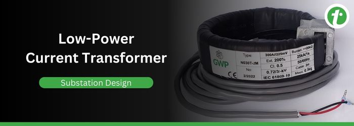
Low Power Current Transformer (LPCT)
A Low Power Current Transformer (LPCT) is a type of current transformer or current sensor used in electrical substations for protection, metering, or conditional monitoring of the electrical power system. It is called LPCT, because it produces a low-voltage analog output in proportion to the primary current, instead of the 1 A or 5 A as in the case of conventional CTs.
- Due to their low power characteristics, LPCTs are mainly used in modern AIS or GIS switchgears and digital substations
- It is also important to note that LPCTs are categorized as Low-Power Instrument Transformer (LPIT) family defined under IEC 61869-6 standard with current transformer requirements in IEC 61869-10 standard.
- In India, low-power current transformers are being used in substations of voltage classes ranging from 33 kV up to 400 kV. They are mostly used in GIS and digital substations.
Read this chapter to learn the basics of Lower Power Current Transformer, its characteristics, and how it differs from a conventional Current Transformer.
Reasons behind Using LPCT in Substations
Listed below are some of the major reasons highlighting the importance of using low power current transformers in substations −
- Mostly, substation designing is adopting IEC 61850 process bus, in which optical fiber ethernet cables are used for connecting LPCTs with metering units and relays, eliminating the need for bulky copper wires/cables.
- LPCTs produce output of the order of millivolts, this feature eliminates the risks of secondary winding short-circuits.
- LPCTs have compact size, hence they are better in terms of space efficiency and suitable to use in urban substations.
- LPCTs with recommended accuracy classes comply with CEA metering regulations.
Standards Related to LPCT in India
The following are some key regulatory standards related to low power current transformers in India −
- IEC 61869-6 − This standard defines the general requirements for low power instrument transformers.
- IEC 61869-10 − This standard defines the requirements specific to low power current transformers.
- CEA Metering Regulation − This regulatory standard mandates 0.2s accuracy class for revenue metering applications.
- CEA Grid Connectivity Standards − These standards define the performance and accuracy of current or potential transformers used for protection applications.
Outputs of LPCTs
Most LPCTs produce secondary output levels of the following standard RMS secondary voltages −
- 22.5 mV
- 150 mV
- 225 mV
In Indian substations, Relays from manufacturers like ABB, Siemens, GE, etc. support LPCT's output in millivolts as input. If some do not support, then a merging unit is used for digitizing signals to IEC 61850-9-2 sampled values.
Difference between LPCT and Conventional CT
The following table highlights the major differences between a low-power current transformer and a conventional current transformer −
| Parameter | Conventional CT | Low Power CT |
|---|---|---|
| Output | It produces a standard output of either 1 A or 5 A. | It produces a standard output of 22.5 mV, 150 mV, or 225 mV. |
| Size | It is larger in size. | It is compact in size. |
| Weight | It is bulky. | It is light in weight. |
| Safety concerns | It has higher risk of secondary short-circuit. | It is safer due to output levels of mV. |
| Saturation | It can saturate at high faults. | It has reduced risk of saturation. |
| Compatibility | It is better suited for legacy relays or metering units. | It is more compatible with digital relays and process bus. |
Characteristics of Low Power Current Transformer
The key characteristics of low power current transformer (LPCT) are explained below −
- Accuracy Class − As per Indian standards, CEA mandates class 0.2s accuracy for energy billing and 5P10/5P20/5P30/5P60 accuracy classes for protection depending on the grid short-circuit levels.
- Fault and Dynamic Performance − In high voltage class substations like 220 kV or 400 kV, fault levels can cross the range of 40-50 kA. In this case, the LPCT must able to withstand such high fault currents. In some applications like GIS substations, Rogowski-base LPCTs are used, as they do not get saturated at high DC offset faults.
- Frequency and Harmonics − LPCTs are capable in handling up to 13th harmonics accurately for supporting power quality monitoring. This characteristics of LPCT becomes more dominating in modern grids where renewable energy integrated with higher harmonic distortion.
- Environmental Conditions − LPCTs are able to operate efficiently in adverse environmental conditions like high ambient temperature, humidity, and dusty conditions.
- Cabling and Shielding − As the output of LPCT is a small single, hence vendor approved shielded cables must be used, also they must be routed carefully in cable trenches with proper earthing.
Advantages of LPCTs
Given below are some of the key benefits of low power current transformers −
- The secondary output voltage is of the order of millivolts and improves the safety.
- Due to compact size and light weight, they are space efficient.
- LPCTs can be seamlessly integrated with process bus in digital substations.
- A single LPCT can be used for multiple purposes i.e., metering and protection.
- LPCTs are compattible with smart grids, SCADA systems, and remote monitoring systems.
Limitations of LPCTs
Apart from the advantages, LPCTs also have some limitations as given below −
- LPCT's output signals are not directly compatible with legacy relays still used in AIS substations, and hence they require merging units.
- Procurement specifications need to be updated.
- Site staff has to be trained about testing and commissioning of LPCTs.
Selection of LPCT in Substation Design
The step-by-step procedure for selecting a correct low power current transformer −
- Step 1 − First of all, check CEA requirements for accuracy class which is 0.2s for energy billing/metering and 5P or 10P for protection.
- Step 2 − Select rated secondary voltage level (Vsr) which can be 22.5 mV/150 mV/225 mV depending on the relay or merging unit requirements.
- Step 3 − Ensure environmental condition suitability such as ambient temperature, dusty, or humidity.
- Step 4 − Ensure the LPCT is compatible with IEC 61850-9-2 LE or IEC 61869-9.
Installation Checklist for LPCT
The following checks must be performed after installation of LPCT and before its energization −
- Verify that the LPCT comply with IEC 61869-6/10 standards, see the nameplate.
- Ensure the LPCT is configured with correct polarity, i.e., P1 → S1, P2 → S2.
- Ensure use of shielded cable for connecting LPCT with relay or metering unit, with single-point grounding.
- Configure relay or metering devices with correct secondary voltage and rated primary current.
- Perform secondary injection and ratio test before energization of the LPCT.
Conclusion
In conclusion, we can state that LPCTs are modern current transformer, being used in electrical substations for metering, protection, or conditional monitoring. They are becoming popular because of their compact size, high safety, and compatibility with digital systems.
