
Article Categories
- All Categories
-
 Data Structure
-
 Networking
-
 RDBMS
RDBMS
-
 Operating System
-
 Java
Java
-
 MS Excel
-
 iOS
iOS
-
 HTML
HTML
-
 CSS
CSS
-
 Android
-
 Python
-
 C Programming
-
 C++
C++
-
 C#
C#
-
 MongoDB
-
 MySQL
MySQL
-
 Javascript
-
 PHP
PHP
-
 Economics & Finance
Single-line and Multiline Diagrams to Represent Electrical Systems
This article is meant for explaining the two most widely used visual representations of electrical systems also called electrical diagrams. These diagrams are single-line diagram and multiline diagram. These two diagrams are used in electrical engineering to represent various electrical layouts and connection arrangements of electrical systems.
In electrical engineering, the visual/graphical representation of electrical systems like distribution systems, control panels, transmission line, generating stations, etc. is very important to understand the connections of various system components, designing and analyzing electrical systems, and more.
In the field of electrical engineering, the following two main types of visual representations are used most commonly
Single-Line Diagram (SLD)
Multiline Diagram (MLD)
Both single-line diagram and multiline diagram are the powerful graphical tools that help to understand the basic structure and connections of components.
To learn everything about single-line diagram (SLD) and multiline diagram (MLD), you should read out this complete article.
What is Single-Line Diagram?
A Single-Line Diagram, also known as SLD, is a type of electrical drawing which is used for representing an electrical system graphically. It is the most simplified visual representation of a complex electrical system.
In a single-line diagram of an electrical system, the main components of the system and their interconnections are depicted with the help of standardized symbols.
The main purpose of a single-line diagram or SLD is to provide a simplified drawing of configuration of a complex electrical system without showing any unnecessary details.
The single-line diagram helps to understand the architecture of an electrical system and provide ease in maintenance work.
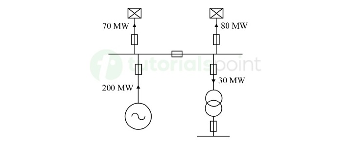
Single-Line Diagram Example
The following figure depicts a typical single-line diagram of an electrical system.
Advantages of Single-Line Diagram
In the field of electrical engineering, the single-line diagrams (SLDs) are of great importance because of the following major advantages
SLD is the most simplified graphical representation of a complex electrical system. Thus, it makes it easier for engineering professionals and technicians to understand the system architecture and interconnections of components.
In a single-line diagram, not all the details about the system are mentioned. Hence, it a compact representation of the system and easy to interpret.
Since SLD is designed using standardized symbols of components. Thus, it is used as a common language for communicating system layouts among designers, engineers, and technicians.
Preparing single-line diagrams is highly time efficient that enables designers and engineers to quickly visualize and interpret different system layouts and optimize them to comply with industry standards and regulations.
A single-line diagram plays a crucial role in maintenance work as it helps engineers and technicians to determine system components and understand their interconnections which is very important in troubleshooting process. Further, the use of SLD greatly reduces the downtime of maintenance work.
Disadvantages of Single-Line Diagram
Although, the single-line diagram (SLD) has several advantages as given above, but it also has some disadvantages or limitations, which are given below
Single-line diagram does not provide detailed information about various components and interconnections of the system. Hence, it is not suitable to understand the complete operation and behavior of an electrical system.
Single-line diagram is a 2D drawing of an electrical system and it does not provide information about physical aspects like cable routing and component placement, etc.
In a complex electrical system, which has some redundant components or multiple alternative paths for cables/wires, the single-line diagram becomes an inefficient visual representation.
The complexity of single-line diagrams increases with the increase in size and complexity of the electrical system. Thus, for very large electrical systems, SLD is not an effective electrical drawing.
Applications of Single-Line Diagram
The single-line diagram (SLD) is used in various applications in the field of electrical engineering. Some of the common applications of single-line diagrams are listed here
Single-line diagrams are used during the initial design stage of electrical systems for planning and conceptualizing the configuration of system components like transformers, generators, distribution panels, circuit breakers, and other.
Single-line diagrams are used for documentation of electrical installations.
Single-line diagrams are also used for specifying the type, rating, and interconnections of electrical components required for a specific application.
Electrical engineers and technicians use single-line diagrams to accomplish installation work of electrical systems.
During the testing and commissioning, single-line diagrams are used to verify that all electrical components of the system have been installed correctly.
During the testing and commissioning, single-line diagrams are used to verify that all electrical components of the system have been installed correctly.
Single-line diagrams are also helpful in upgrading or modifying the existing electrical systems.
This is all about single-line diagrams and their advantages and applications in electrical design and system representation. SLDs are one of the important electrical drawings used in various applications like designing, maintenance, and operation of electrical systems and they provide a standardized method for representing and understanding complex electrical systems.
Let us now learn about another electrical drawing called multiline diagram of electrical systems.
What is Multiline Diagram?
In electrical design drawing, a multiline diagram is a graphical tool used for visualizing three-phase electrical power systems or power delivery networks. Thus, it is also known as three-line diagram. In a typical multiline diagram, we use multiple parallel lines to depict the different phases and circuit components of the electrical system.
Similar to single-line diagrams, the multiline diagrams are also used in electrical design and documentation applications. Using multiline diagrams, electrical engineers and technicians can obtain more detailed and accurate information about the electrical infrastructure.
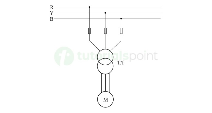
Multiline Diagram Example
An example of multiline diagram of an electrical system is shown in the following figure.
Advantages of Multiline Diagram
Multiline diagrams are extensively used for representing three-phase electrical systems graphically because of the following major advantages
Multiline diagram allows us to represent each phase of a three-phase electrical system separately by using parallel lines. This gives a clear and detailed visualization of a multiphase electrical system.
In distribution networks, multiline diagrams provide a way of illustrating busbars and conductors differently. Where, busbars are visualized as thick lines, while conductors are represented as thin lines.
Multiline diagrams provide a detailed view of interconnections between circuit components like transformers, generators, circuit breakers, and electrical loads.
Multiline diagrams are effective in representing large and complex electrical systems.
Disadvantages of Multiline Diagram
However, multiline diagrams offer several advantages as mentioned above, but they also have some disadvantages/limitations over single-line diagrams as listed below
Multiline diagrams are relatively more complex as compared to single-line diagrams. This is because they use separate representation of each phase using parallel lines.
Multiline diagrams are relatively harder to understand and interpret for personals who are not having knowledge of electrical engineering.
Multiline diagrams use more lines and symbols; hence they require more space than single-line diagrams to represent electrical systems.
Sometimes, multiline diagrams can be confusing due to use of multiple lines. It happens more when lines intersect or overlap. Thus, a clear and proper labeling and organization of lines and components is required.
Multiline diagrams involve more complex documentation of electrical systems.
Multiline diagrams are less consistent and standardized across different industries, areas, and organizations.
For multiline diagrams, it is relatively difficult to modify and update them and they require more attention while revising.
Multiline diagrams are more prone to errors and inconsistencies.
Applications of Multiline Diagram
In the field of electrical engineering, multiline diagrams are used in the design and documentation of complex electrical systems. Some examples of applications of multiline diagrams are listed below
Multiline diagrams are extensively used in electrical designs of power systems, substations, distribution systems, and other industrial electrical systems.
Multiline diagrams are also used for graphical representation of three-phase electrical systems.
Multiline diagrams also play an important role in load flow analysis in power systems, as they allow engineers to model the flow of current and power between nodes and analyze the performance of the systems to meet the specific requirements.
Multiline diagrams act as detailed document of an electrical system and provide complete information about various electrical installations within the system.
Conclusion
In electrical engineering, both single-line diagram (SLD) and multiline diagram (MLD) are essential tools used for design and documentation purposes of electrical systems.
A single-line diagram is a most simplified graphical representation of electrical systems in which standard symbols and lines are used to represent interconnections of the system. SLDs are mainly used for initial design and basic documentation purposes, and they are not suitable for representation of complex systems accurately.
On the other side, a multiline diagram is a more detailed representation of an electrical system and provides all the important information about the system architecture, phase relationship, and more. Multiline diagrams are powerful design tools for representation and documentation of large and complex electrical systems like power distribution networks.
Overall, both single-line diagram and multiline diagram are used as the design and communication tools in electrical engineering.

3K+ Views
