
Article Categories
- All Categories
-
 Data Structure
-
 Networking
-
 RDBMS
RDBMS
-
 Operating System
-
 Java
Java
-
 MS Excel
-
 iOS
iOS
-
 HTML
HTML
-
 CSS
CSS
-
 Android
-
 Python
-
 C Programming
-
 C++
C++
-
 C#
C#
-
 MongoDB
-
 MySQL
MySQL
-
 Javascript
-
 PHP
PHP
-
 Economics & Finance
Serial Filtering Library in Arduino
The Serial filtering library in Arduino helps you to apply some low pass filters and the median filter on any incoming data, to give you the filtered output. The GitHub repo of this library can be found here, and it is pretty detailed.
In order to install the library, download the source code from GitHub, and place the 'Filter' folder in the libraries folder of Arduino (on Windows, the path is typically: C:/Users/
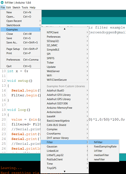
Once that is done, in the Arduino IDE, open File→Examples→Filter and pick an example of your choice (firFilter for example)
As you can see, the code is quite straightforward.
#include <firFilter.h>

firFilter Filter;

int value;
int filtered;

void setup()
{
   Serial.begin(115200);
   Filter.begin();
}

void loop()
{
   value = analogRead(A0);
   filtered= Filter.run(value);
   Serial.print("In: ");
   Serial.print(value);
   Serial.print(" - Out: ");
   Serial.println(filtered);
   delay(100);                // make it readable
}
It is taking an incoming analogRead value, applying the filter on it, and returning the output value.
In fact, if you don't have an analog source available, we can test the filter using the random() function. Have a look at the modified example below −
#include <firFilter.h>

firFilter Filter;

int value;
int filtered;
int x = 0;

void setup()
{
   Serial.begin(9600);
   Filter.begin();
}

void loop()
{
   value = (sin(x*3.14/180) + random(100)*1.0/50)*100.0;
   filtered= Filter.run(value);
   //Serial.print("In: ");
   Serial.print(value);
   Serial.print(',');
   //Serial.print(" - Out: ");
   Serial.println(filtered);
   delay(50); //make it readable
   x = x+1;
}
We have added noise to a sine wave. If we look at the Serial Plotter output, this is what it looks like −
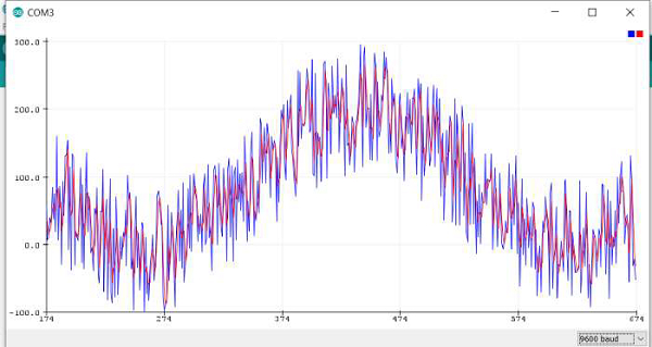
Blue line represents the original signal, and red line represents the filtered signal. As you can see, the blue one is noisier than the red, meaning the filter seems to be working.
You can play around with the other filters that come with this library.

1K+ Views
