
Article Categories
- All Categories
-
 Data Structure
-
 Networking
-
 RDBMS
RDBMS
-
 Operating System
-
 Java
Java
-
 MS Excel
-
 iOS
iOS
-
 HTML
HTML
-
 CSS
CSS
-
 Android
-
 Python
-
 C Programming
-
 C++
C++
-
 C#
C#
-
 MongoDB
-
 MySQL
MySQL
-
 Javascript
-
 PHP
PHP
Selected Reading
Return if carry (RC) in 8085 Microprocessor
In 8085 Instruction set, RC is a mnemonic, which stands for “Return if Carry”. This instruction is used to return to the main program, only if Cy flag value is 1. If Cy flag value is 0, program flow continues in the subroutine sequentially. It is a 1-Byte instruction.
| Mnemonics, Operand |
Opcode(in HEX) |
Bytes |
|---|---|---|
| RC |
D8 |
1 |
Let us consider the following sample code for a better explanation –
| Address |
Hex Codes |
Mnemonic |
Comment |
|---|---|---|---|
| 2000 |
31 |
LXI SP, 5000H |
SP ← 5000H.Initializing the SP |
| 2001 |
00 |
|
Low order Byte of the address |
| 2002 |
50 |
|
High order Byte of the address |
| 2003 |
21 |
LXI H, 4050H |
HL ← 4050H, Initializing the HL register pair |
| 2004 |
50 |
|
Low order Byte of the address |
| 2005 |
40 |
|
High order Byte of the address |
| 2006 |
CD |
CALL 200BH |
Calling the subroutine at address 200BH. So now the control of the program will be transferred to the location 200BH. And the return address 2009H i.e. address of the next instruction will be pushed on the top of the stack. As a result 4FFFH (SP – 1) will contain 20H and 4FFEH (SP – 2) will contain 09H respectively. |
| 2007 |
0B |
|
Low order Byte of the address |
| 2008 |
20 |
|
High order Byte of the address |
| 2009 |
77 |
MOV M, A |
M ← A, Content of the Accumulator will be transferred to the memory location 4050H as it is pointed by HL register pair. So at 4050H memory location Accumulators, content F0H will be stored. After successful execution of the RC instruction, control will come back to this instruction. |
| 200A |
76 |
HLT |
End of the program. |
| 200B |
3E |
MVI A, 40H |
A ← 40H, Initializing the Accumulator with initial value 40H |
| 200C |
40 |
|
40H as operand |
| 200D |
06 |
MVI B, 50H |
B ← 50H, Initializing the Register B with initial value 30H |
| 200E |
50 |
|
50H as operand |
| 200F |
90 |
SUB B |
A ← A – B= 40H – 50H = -10H = F0H, As the computed result has got generate with carry, so Cy = 1 |
| 2010 |
D8 |
RC |
Return the control to the address 2009H. Return address 2009H will be popped out from the top of the stack. So from address 4FFEH, 09H will be popped and from address 4FFFH, 20Hwill be popped and SP will get the initial address 5000H back as its content accordingly. |
| 2011 |
80 |
ADD B |
A ← A + B ← -10H + 50H = 40H. (But in this example this line is unreachable, so will not get executed) |
| 2012 |
77 |
MOV M, A |
M ← A, Content of the Accumulator will be transferred to the memory location 4050H as it is pointed by HL register pair. So at 4050H memory location Accumulators content 40H will be stored. (But in this example this line is unreachable, so will not get executed) |
| 2013 |
C9 |
RET |
Return the control to the address 2009H. Return address 2009H will be popped out from the top of the stack. So from address 4FFEH, 09H will be popped and from address 4FFFH 20H will be popped and SP will get the initial address 5000H back as its content accordingly. (But in this example this line is unreachable, so will not get executed) |
The timing diagram against this instruction RC execution is as follows –
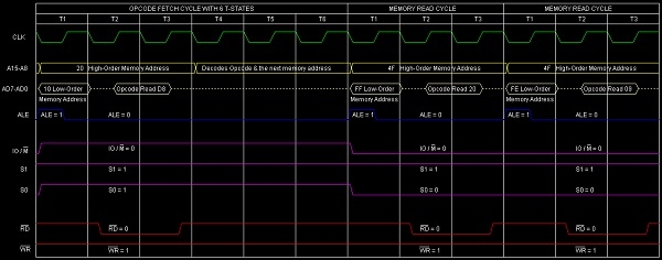
Summary − So this instruction RC requires 1-Byte, 3-Machine Cycles (Opcode Fetch, Memory Read, Memory Read) and 12 T-States for execution as shown in the timing diagram.

Updated on: 2020-06-27T14:16:45+05:30
887 Views

Advertisements