
Article Categories
- All Categories
-
 Data Structure
-
 Networking
-
 RDBMS
RDBMS
-
 Operating System
-
 Java
Java
-
 MS Excel
-
 iOS
iOS
-
 HTML
HTML
-
 CSS
CSS
-
 Android
-
 Python
-
 C Programming
-
 C++
C++
-
 C#
C#
-
 MongoDB
-
 MySQL
MySQL
-
 Javascript
-
 PHP
PHP
-
 Economics & Finance
Potential Distribution over a Suspension Insulator String
Suspension Insulator
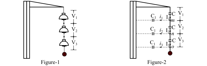
The suspension type insulator is the one which consists of a number of porcelain discs connected in series by metal links in the form of a string as shown in Figure-1.
Potential Distribution over Suspension Insulator String
As we know the string of suspension insulators consists of a number of porcelain discs connected in series through metal links. The porcelain portion of each disc is in between two metal links. Thus, the disc acts like a capacitor represented by C as shown in Figure-2.
The capacitance C is called the mutual capacitance. If the string has only mutual capacitance, then the charging current would have been the same through all the discs and hence, the voltage across each disc would have been the same (say V/3) as shown in Figure-2. But in actual practice, a capacitance also exists between the metal fitting of each disc and the tower. This capacitance is called the shunt capacitance, represented by C1 in the Figure-2.
Due to the presence of the shunt capacitance, the charging current is not the same through all the discs of the string, i.e. the voltage across each disc will be different. The disc nearest to the line conductor will have the maximum voltage.
Therefore, the important points observed regarding the potential distribution over a string of suspension insulators are as follows −
The voltage across a string of suspension insulators does not distributes itself uniformly across the individual discs due to the presence of shunt capacitance.
The disc nearest to the line conductor has maximum voltage across it and it decreases as the cross-arm is approached.
If the voltage applied across the string is DC, then the voltage across each disc would be the same because the insulator capacitances are ineffective for DC.
Mathematical Analysis of Potential Distribution over Suspension Insulator String
Refer Figure-2. Let the shunt capacitance C1 is some fraction K of self-inductance (C), i.e., ?1=??. Starting from the cross-arm, the voltage across each disc is V1, V2 and V3, respectively.
Applying KCL to node m, we have,
$$\mathrm{\mathit{I_{\mathrm{2}}\mathrm{\, =\, }I_{\mathrm{1}}\mathrm{\, +\, }i_{\mathrm{1}}}}$$
$$\mathrm{\mathit{\Rightarrow \omega \, CV_{\mathrm{2}}\mathrm{\, =\, }\omega \, CV_{\mathrm{1}}\mathrm{\, +\, }\omega \, C_{\mathrm{1}}V_{\mathrm{1}}}}$$
$$\mathrm{\mathit{\Rightarrow \omega \, CV_{\mathrm{2}}\mathrm{\, =\, }\omega \, CV_{\mathrm{1}}\mathrm{\, +\, }\omega \, KCV_{\mathrm{1}}}}$$
$$\mathrm{\mathit{\Rightarrow V_{\mathrm{2}}\mathrm{\, =\, }V_{\mathrm{1}}\left ( \mathrm{1}\mathrm{\, +\, }K \right )}\: \: \: \cdot \cdot \cdot \left ( 1 \right )}$$
Applying KCL to node n, we have,
$$\mathrm{\mathit{I_{\mathrm{3}}\mathrm{\, =\, }I_{\mathrm{2}}\mathrm{\, +\, }i_{\mathrm{2}}}}$$
$$\mathrm{\mathit{\Rightarrow \omega \, CV_{\mathrm{3}}\mathrm{\, =\, }\omega \, CV_{\mathrm{2}}\mathrm{\, +\, }\omega \, C_{\mathrm{1}}\left ( V_{\mathrm{1}}\mathrm{\, +\, }V_{\mathrm{2}} \right )}}$$
$$\mathrm{\mathit{\Rightarrow \omega \, CV_{\mathrm{3}}\mathrm{\, =\, }\omega \, CV_{\mathrm{2}}\mathrm{\, +\, }\omega \, KC\left ( V_{\mathrm{1}}\mathrm{\, +\, }V_{\mathrm{2}} \right )}}$$
$$\mathrm{\mathit{\Rightarrow V_{\mathrm{3}}\mathrm{\, =\, }V_{\mathrm{2}}\mathrm{\, +\, }\left ( V_{\mathrm{1}}\mathrm{\, +\, }V_{\mathrm{2}} \right )K}} $$
$$\mathrm{\mathit{\Rightarrow V_{\mathrm{3}}\mathrm{\, =\, }KV_{\mathrm{1}}\mathrm{\, +\, }V_{\mathrm{2}}\left ( \mathrm{1}\mathrm{\, +\, }K \right )}}$$
$$\mathrm{\mathit{\Rightarrow V_{\mathrm{3}}\mathrm{\, =\, }KV_{\mathrm{1}}\mathrm{\, +\, }V_{\mathrm{1}}\left ( \mathrm{1}\mathrm{\, +\, }K \right )^{\mathrm{2}}\mathrm{\, =\, }V_{\mathrm{1}}\left [ K\mathrm{\, +\, }\left ( \mathrm{1}\mathrm{\, +\, }K \right )^{\mathrm{2}} \right ]}}$$
$$\mathrm{\mathit{\therefore V_{\mathrm{3}}\mathrm{\, =\, }V_{\mathrm{1}}\left [ \mathrm{1\mathrm{\, +\, }3}K\mathrm{\, +\, }K^{\mathrm{2}} \right ] }\: \: \: \cdot \cdot \cdot \left ( 2 \right )}$$
Now, the voltage between the conductor and cross-arm is
$$\mathrm{\mathit{V\mathrm{\, =\, }V_{\mathrm{1}}\mathrm{\, +\, }V_{\mathrm{2}}\mathrm{\, +\, }V_{\mathrm{3}}}}$$
$$\mathrm{\mathit{V\mathrm{\, =\, }V_{\mathrm{1}}\mathrm{\, +\, }V_{\mathrm{1}}\left ( \mathrm{1}\mathrm{\, +\, }K \right )\mathrm{\, +\, }V_{\mathrm{1}}\left [ \mathrm{1\mathrm{\, +\, }3}K\mathrm{\, +\, }K^{\mathrm{2}} \right ]}}$$
$$\mathrm{\mathit{\Rightarrow V\mathrm{\, =\, }V_{\mathrm{1}}\left (K^{\mathrm{2}}\mathrm{\, +\, } \mathrm{4}K \mathrm{\, +\, }\mathrm{3}\right )}}$$
$$\mathrm{\mathit{\therefore V\mathrm{\, =\, }V_{\mathrm{1}}\left (\mathrm{1}\mathrm{\, +\, }K\right )\left ( \mathrm{3}\mathrm{\, +\, }K \right )}\: \: \: \cdot \cdot \cdot \left ( 3 \right )} $$
From equations (1), (2) & (3), we get,
$$\mathrm{\mathit{\frac{V_{\mathrm{1}}}{\mathrm{1}}\mathrm{\, =\, }\frac{V_{\mathrm{2}}}{\left ( \mathrm{1}\mathrm{\, +\, }K \right )}\mathrm{\, =\, }\frac{V_{\mathrm{3}}}{\left ( \mathrm{1\mathrm{\, +\, }3}K\mathrm{\, +\, }K^{\mathrm{2}} \right )}\mathrm{\, =\, }\frac{V}{\left ( \mathrm{1}\mathrm{\, +\, }K \right )\left ( \mathrm{3} \mathrm{\, +\, }K\right )} }\: \: \: \cdot \cdot \cdot \left ( 4 \right )}$$
Therefore, the voltage across each disc be given by,
$\mathrm{Voltage\: across\: top\: disc,\mathit{V_{\mathrm{1}}\mathrm{\, =\, }\frac{V}{\left ( \mathrm{1}\mathrm{\, +\, }K \right )\left ( \mathrm{3} \mathrm{\, +\, }K\right )}}}$
$\mathrm{Voltage \: across\: 2^{nd}\: disc\: from\: top,\mathit{V_{\mathrm{2}}\mathrm{\, =\, }\frac{V}{\left ( \mathrm{3} \mathrm{\, +\, }K\right )}\mathrm{\, =\, }V_{\mathrm{1}}\left ( \mathrm{1}\mathrm{\, +\, }K \right )}}$
$\mathrm{Voltage\: across\: 3^{rd}\: disc\: from\: top,\mathit{V_{\mathrm{3}}\mathrm{\, =\, }V_{\mathrm{1}}\left ( \mathrm{1}\mathrm{\, +\, }\mathrm{3}K\mathrm{\, +\, }K^{\mathrm{2}} \right )}}$
Hence, the following points can be observed from the above mathematical analysis −
Let K = 0.3, then from equation (4), we have V2 = 1.3 V1 and V3 = 1.99 V1. This shows that the disc nearest to the conductor has maximum voltage across it.
The greater the value of K, the more non-uniform is the voltage across the discs of the string and hence, lesser is string efficiency.
The inequality in the potential distribution increases with the increase in the number of discs in the string of insulators.

7K+ Views
