
Article Categories
- All Categories
-
 Data Structure
-
 Networking
-
 RDBMS
RDBMS
-
 Operating System
-
 Java
Java
-
 MS Excel
-
 iOS
iOS
-
 HTML
HTML
-
 CSS
CSS
-
 Android
-
 Python
-
 C Programming
-
 C++
C++
-
 C#
C#
-
 MongoDB
-
 MySQL
MySQL
-
 Javascript
-
 PHP
PHP
Negative Booster in Electric Traction
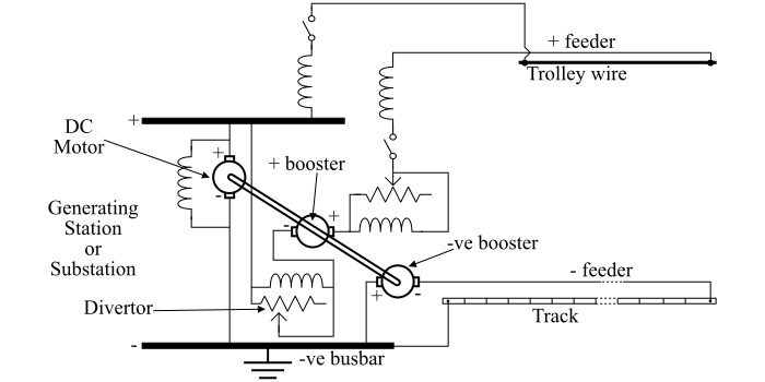
A negative booster is a separately excited DC generator whose armature is connected with negative bus-bar at the far end of the track through negative feeder. The connection diagram of the negative booster is shown in the figure below.
As in case of DC traction system, the return current flows through the rails to the substations. Because of this current flow through the rails, some voltage drop exists along the track. Due to potential difference along the track, some of the return currents leak out to the earth and follow the path of low resistance provided by water pipes, gas pipes, cable sheaths, etc.
These leakage currents cause electrolytic corrosion to occur at the places where the current leaves the pipes as they carry the metal of the pipe to the electrolytic solution, where pipe acts as anode and the moisture and salts in the surrounding soil act as electrolytic solution.
According to the statutory regulations, the voltage drop in the rails is limited to 7 volts and the voltage between the pipe and rails is limited to 1 volt positive and 3 volts negative, so that the corrosion of pipes and cable sheaths adjacent to the track is to be minimized.
Methods to Maintain the Voltage Drop
The following three methods are used for maintaining the voltage drop in the track rails within the limit of 7 volts −
By making the return path of very low resistance, which may be achieved by providing good bonds or by using insulated negative feeders.
By discouraging the entry of current into the pipes by inserting occasional insulating joints.
By employing negative booster.
From the connection diagram of the negative booster, it can be seen that the negative bus-bar is connected to the track rail through negative feeder and the positive bus-bar is connected to the trolley wire near the generating stations.
In the whole assembly, there are two boosters used, one is positive booster which adds voltage to the line and the other is the negative booster which lowers the potential of the point to which it is connected. Both the boosters are mechanically coupled together and are driven by a DC motor.
Actually, the negative booster is the separately excited DC generator whose armature is connected with the negative bus-bar at the far end of the track through negative feeder. The field winding of the negative booster is connected in series with the positive feeder supplying the corresponding sections of the trolley wire.
The boost of the feeder is adjusted by means of a diverter rheostat connected in parallel with the field winding of the positive booster.

2K+ Views
