- LTE - Home
- LTE - Overview
- LTE - Basic Parameters
- LTE - Network Architecture
- LTE - Roaming Architecture
- LTE - Numbering & Addressing
- LTE - Radio Protocol Architecture
- LTE - Protocol Stack Layers
- LTE - Layers Data Flow
- LTE - Communication Channels
- LTE - OFDM Technology
- LTE - Glossary
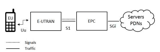
LTE Network Architecture
The high-level network architecture of LTE is comprised of following three main components:
The User Equipment (UE).
The Evolved UMTS Terrestrial Radio Access Network (E-UTRAN).
The Evolved Packet Core (EPC).
The evolved packet core communicates with packet data networks in the outside world such as the internet, private corporate networks or the IP multimedia subsystem. The interfaces between the different parts of the system are denoted Uu, S1 and SGi as shown below:
The User Equipment (UE)
The internal architecture of the user equipment for LTE is identical to the one used by UMTS and GSM which is actually a Mobile Equipment (ME). The mobile equipment comprised of the following important modules:
Mobile Termination (MT) : This handles all the communication functions.
Terminal Equipment (TE) : This terminates the data streams.
Universal Integrated Circuit Card (UICC) : This is also known as the SIM card for LTE equipments. It runs an application known as the Universal Subscriber Identity Module (USIM).
A USIM stores user-specific data very similar to 3G SIM card. This keeps information about the user's phone number, home network identity and security keys etc.
The E-UTRAN (The access network)
The architecture of evolved UMTS Terrestrial Radio Access Network (E-UTRAN) has been illustrated below.
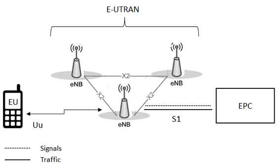
The E-UTRAN handles the radio communications between the mobile and the evolved packet core and just has one component, the evolved base stations, called eNodeB or eNB. Each eNB is a base station that controls the mobiles in one or more cells. The base station that is communicating with a mobile is known as its serving eNB.
LTE Mobile communicates with just one base station and one cell at a time and there are following two main functions supported by eNB:
The eBN sends and receives radio transmissions to all the mobiles using the analogue and digital signal processing functions of the LTE air interface.
The eNB controls the low-level operation of all its mobiles, by sending them signalling messages such as handover commands.
Each eBN connects with the EPC by means of the S1 interface and it can also be connected to nearby base stations by the X2 interface, which is mainly used for signalling and packet forwarding during handover.
A home eNB (HeNB) is a base station that has been purchased by a user to provide femtocell coverage within the home. A home eNB belongs to a closed subscriber group (CSG) and can only be accessed by mobiles with a USIM that also belongs to the closed subscriber group.
The Evolved Packet Core (EPC) (The core network)
The architecture of Evolved Packet Core (EPC) has been illustrated below. There are few more components which have not been shown in the diagram to keep it simple. These components are like the Earthquake and Tsunami Warning System (ETWS), the Equipment Identity Register (EIR) and Policy Control and Charging Rules Function (PCRF).
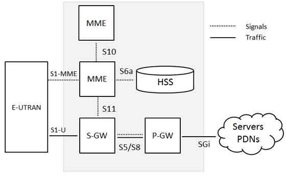
Below is a brief description of each of the components shown in the above architecture:
The Home Subscriber Server (HSS) component has been carried forward from UMTS and GSM and is a central database that contains information about all the network operator's subscribers.
The Packet Data Network (PDN) Gateway (P-GW) communicates with the outside world ie. packet data networks PDN, using SGi interface. Each packet data network is identified by an access point name (APN). The PDN gateway has the same role as the GPRS support node (GGSN) and the serving GPRS support node (SGSN) with UMTS and GSM.
The serving gateway (S-GW) acts as a router, and forwards data between the base station and the PDN gateway.
The mobility management entity (MME) controls the high-level operation of the mobile by means of signalling messages and Home Subscriber Server (HSS).
The Policy Control and Charging Rules Function (PCRF) is a component which is not shown in the above diagram but it is responsible for policy control decision-making, as well as for controlling the flow-based charging functionalities in the Policy Control Enforcement Function (PCEF), which resides in the P-GW.
The interface between the serving and PDN gateways is known as S5/S8. This has two slightly different implementations, namely S5 if the two devices are in the same network, and S8 if they are in different networks.
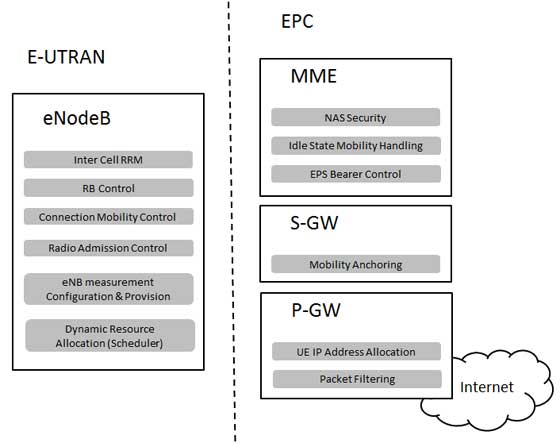
Functional split between the E-UTRAN and the EPC
Following diagram shows the functional split between the E-UTRAN and the EPC for an LTE network:
2G/3G Versus LTE
Following table compares various important Network Elements & Signaling protocols used in 2G/3G abd LTE.
| 2G/3G | LTE |
|---|---|
| GERAN and UTRAN | E-UTRAN |
| SGSN/PDSN-FA | S-GW |
| GGSN/PDSN-HA | PDN-GW |
| HLR/AAA | HSS |
| VLR | MME |
| SS7-MAP/ANSI-41/RADIUS | Diameter |
| DiameterGTPc-v0 and v1 | GTPc-v2 |
| MIP | PMIP |
