 Data Structure
 Networking
 RDBMS
RDBMS Operating System
 Java
Java MS Excel
 iOS
iOS HTML
HTML CSS
CSS Android
 Python
 C Programming
 C++
C++ C#
C# MongoDB
 MySQL
MySQL Javascript
 PHP
PHP
- Selected Reading
- UPSC IAS Exams Notes
- Developer's Best Practices
- Questions and Answers
- Effective Resume Writing
- HR Interview Questions
- Computer Glossary
- Who is Who
Implementation of connection-oriented services
We need a virtual-circuit subnet for connection-oriented service. Virtual circuits were designed to avoid having to choose a new route for every packet sent.
Instead, a route from the source machine to the destination machine is chosen as part of the connection setup and stored in tables inside the routers, when a connection is established. That route is utilised for all traffic flowing over the connection, and exactly the same manner even telephone works.
The virtual circuit is also terminated, when the connection is released. In connection-oriented service, every packet will have an identifier which tells to which virtual circuit it belongs to.
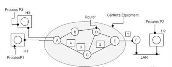
The implementation of connection-oriented services is diagrammatically represented as follows −

Example
Consider the scenario as mentioned in the above figure.
Step 1 − Host H1 has established connection 1 with host H2, which is remembered as the first entry in every routing table.
Step 2 − The first line of A’s infers when packet is having connection identifier 1 is coming from host H1 and has to be sent to router W and given connection identifier as 1.
Step 3 − Similarly, the first entry at W routes the packet to Y, also with connection identifier 1.
Step 4 − If H3 also wants to establish a connection to H2 then it chooses connection identifier 1 and tells the subnet to establish the virtual circuit. This will be appearing in the second row in the table.
Step 5 − Note that we have a conflict here because although we can easily distinguish connection 1 packets from H1 from connection 1 packet from H3, W cannot do this.
Step 6 − For this reason, we assign a different connection identifier to the outgoing traffic for the second connection. Avoiding conflicts of this kind is why routers need the ability to replace connection identifiers in outgoing packets. In some contexts, this is called label switching.

