
Article Categories
- All Categories
-
 Data Structure
-
 Networking
-
 RDBMS
RDBMS
-
 Operating System
-
 Java
Java
-
 MS Excel
-
 iOS
iOS
-
 HTML
HTML
-
 CSS
CSS
-
 Android
-
 Python
-
 C Programming
-
 C++
C++
-
 C#
C#
-
 MongoDB
-
 MySQL
MySQL
-
 Javascript
-
 PHP
PHP
-
 Economics & Finance
Flip-Flop Used as a Divider Circuit
Let's start this article with a basic overview of flip-flops before moving onto discuss how they can be used as a divider circuit.
What is a Flip-Flop?
In digital electronics, a flip-flop (FF) is a sequential logic circuit which is used for storing 1-bit of information. As we know, in digital systems, information is represented in binary form, i.e. in terms of 0 and 1. Where, a binary 0 and a binary 1 is referred to as a bit.
A flip-flop is a 1-bit memory cell that stores information in terms of 0 or 1. Therefore, flipflop is the fundamental memory element in all digital systems.
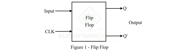
A flip-flop has one or more inputs and two outputs. Where, one is the normal output denoted by Q and the other is inverted output denoted by Q'. Hence, a flip-flop has two stable states due to which it is also known as bistable multivibrator.
The logic symbol diagram of a typical flip-flop is shown in Figure-1.
After knowing the basics of flip-flops, now let us discuss how they can be used as a divider circuit.
Flip-Flop used as a Divider Circuit
We can use a flip-flop as a divider circuit just by connecting its outputs back to its inputs. This connection between input and output creates a feedback path that causes the flip-flop to toggle between its two stable states.
We can adjust the timing of the input signal to divide the frequency of the output by a factor of two.
To understand the functioning of a flip-flop as a divider circuit, let us consider an example of a D flip-flop in which the output of the D flip-flop, i.e. Q' is connected to its input D as shown in the Figure-2 below.
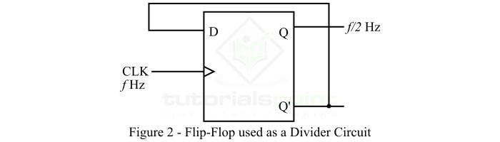
Here, a clock signal (denoted by CLK) is used to trigger the flip-flop to change the state of its output. When the clock pulse goes from low to high, the flip-flop accepts the values of its input D and updates the output Q according to the input value.
However, the output Q' is fed back to the input D, therefore, the flip-flop will continue to toggle its output between its two states as long as the clock pulse is present.
Now, let us consider if a square wave signal is applied to the clock input of the flip-flop having a frequency equal to ?. Then, the output of the flip-flop will also be a square wave signal having a frequency of ?/2 because the output state of the flip-flop changes on every rising edge of the clock pulse. Therefore, it effectively divides the frequency by a factor of two.
Therefore, from the above discussion it is clear that the basic principle of using a flip-flop as a divider circuit is the feedback from input to output to create a toggling effecting.
Now, let us discuss the applications of flip-flop as a divider circuit.
Applications of Flip-Flop as a Divider Circuit
In electronics and digital systems, flip-flop as a divider circuit has several applications. Some of the common applications of a flip-flop used as a divider circuit are listed below ?
The flip-flop divider circuit is primarily used to divide the frequency of a signal by a constant factor.
Flip-flop divider circuit is used in digital circuits where different circuit components require different clock speeds for operation.
Flip-flop divider circuits are also used to generate clock pulses of specific frequencies.
Flip-flop divider circuits can also be used in binary counting.
Flip-flop divider circuits can also be employed for pulse shaping.
Flip-flop divider circuit can be used to filter out noise and unwanted signals from digital signals.
Conclusion
This is all about flip-flop as a divider circuit. In conclusion, flip-flop used as a divider circuit is an important component of digital circuits. It is primarily used to divide the frequency of a signal by a fixed factor. Hence, it has applications in a wide range of electronic devices and circuits.

2K+ Views
