
Article Categories
- All Categories
-
 Data Structure
-
 Networking
-
 RDBMS
RDBMS
-
 Operating System
-
 Java
Java
-
 MS Excel
-
 iOS
iOS
-
 HTML
HTML
-
 CSS
CSS
-
 Android
-
 Python
-
 C Programming
-
 C++
C++
-
 C#
C#
-
 MongoDB
-
 MySQL
MySQL
-
 Javascript
-
 PHP
PHP
-
 Economics & Finance
Explain Mapping the ER diagrams with binary and ternary relationships(DBMS)?
It is the relationship between the instances of two different entity types. Two entities will participate in the relationship.
Example
Person and events are two different entity types which are related by using the relationship called “attends”.

Mapping ER diagram with binary relationship
Mapping one to many relationship
Example
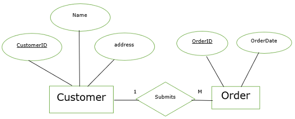
Here,
Create two tables for two entities.
Primary key of one side relation is a foreign key for many side relations.
One side relation is customer and many side relations is Order.
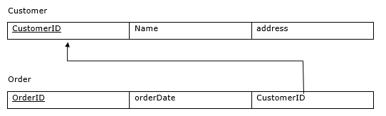
The primary key cutomerID of the customer is a foreign key of order.
The equivalent relations for the above ER diagram are as follows −
One-one, many-one, many-many can be done in a similar fashion.
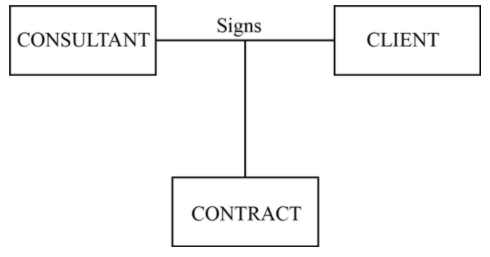
Ternary relationship
A simultaneous relationship between the instances of three entity types with unique attributes is called a ternary relationship.
Example
Consultant, client and contract are three different entities with different attributes.
These three entities are related with a single relationship called “signs”.
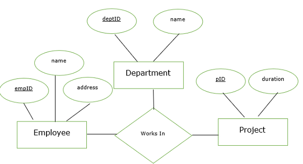
Here,
Three foreign keys of works in the table are empID, deptID, pID.
They refer to the primary key of an employee, department, project.
These attributes are the component of the primary key of works in table.
The primary key works in the table is (empID,depID,pID).
The equivalent relation for the above ER diagram is as follows −
Employee
| empID | name | address |
Department
| deptID | name |
Project
| pID | duration |
Works In
| empID | deptID | pID | dateofjoin |

4K+ Views
