
Article Categories
- All Categories
-
 Data Structure
-
 Networking
-
 RDBMS
RDBMS
-
 Operating System
-
 Java
Java
-
 MS Excel
-
 iOS
iOS
-
 HTML
HTML
-
 CSS
CSS
-
 Android
-
 Python
-
 C Programming
-
 C++
C++
-
 C#
C#
-
 MongoDB
-
 MySQL
MySQL
-
 Javascript
-
 PHP
PHP
-
 Economics & Finance
Difference between RL and RC Circuit
A closed path followed by electric current is known as electric circuit. Based on the type of electric supply, the electric circuits can be classified into two major types viz. DC circuit and AC circuit.
Every electric circuit consists of a number of circuit elements such as energy sources, resistors, inductors, capacitors, etc. In a DC circuit only resistors are meaningful, because the inductor and capacitor are the frequency dependent elements and for DC supply the frequency is zero. On the other hand, all the three elements, i.e. resistors, inductors and capacitors are functional in an AC circuit.
Based on the combination of circuit elements used in the circuits, they can be classified into following types
RL Circuit
RC Circuit
RLC Circuit
But, in this article, we will focus only on the major differences between RL circuit and RC circuit. Also, we will briefly describe the RL and RC circuits, which makes it easy to understand of differences between them.
What is an RL Circuit?
When a resistor is connected with an inductor, either in series or parallel, and this combination is connected across a source of power, then the resulting circuit known as RL circuit. Based on the connection of resistor and inductor, the circuit may be series RL circuit or parallel RL circuit.
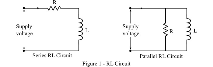
A typical series RL circuit and parallel RL circuit is known in Figure-1. At this point we are assuming the series RL circuit for explaining the differences.
When circuit is closed, a current starts flowing through the circuit. In RL circuit, the energy is consumed in two phenomena viz. dissipated as heat by the resistor and stored in magnetic field of the inductor. This energy stored in the magnetic field of the inductor can be expressed in terms of inductance of the inductor (L) and circuit current (I). For an RL circuit, the expressions of voltage, current and energy stored are as follows
$$\mathrm{\mathrm{Voltage,\mathit{V}}\:=\:\mathit{iR}+\mathit{L\frac{di}{dt}}}$$
$$\mathrm{\mathrm{Current,\mathit{i}}\:=\:\frac{\mathit{V}}{\mathit{R}}\mathrm{\left( \mathrm{1-\mathit{e^{-\frac{Rt}{L}}}}\right )}}$$
$$\mathrm{\mathrm{Energy\:stored},\mathit{W}\:=\:\frac{\mathrm{1}}{\mathrm{2}}\mathit{Li^{\mathrm{2}}}}$$
The practical example of RL circuits are windings of motors, generators, transformers, and transmission lines, etc.
What is an RC Circuit?
When a resistor is connected in series or parallel of a capacitor, then the circuit is known as RC circuit. Based on the connection type, it may be series RC circuit or parallel RC circuit. Figure-2 shows the series and parallel RC circuits.
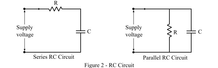
The RC circuit stores the energy in the form of electrostatic field. It is because the capacitor has the ability to store the electric charge between its plates. This stored energy can be expressed in terms of capacitance of the capacitor and voltage. The expressions of voltage, current and energy stored in the RC circuit are given as follows
$$\mathrm{\mathrm{Voltage,\mathit{V}}\:=\:\mathit{iR}+\mathit{V_{c}}}$$
$$\mathrm{\mathrm{Current,\mathit{i}}\:=\:\frac{\mathit{V}}{\mathit{R}}\mathrm{\left( \mathrm{\mathit{e^{-\frac{t}{RC}}}}\right )}}$$
$$\mathrm{\mathrm{Energy\:stored},\mathit{W}\:=\:\frac{\mathrm{1}}{\mathrm{2}}\mathit{CV^{\mathrm{2}}}}$$
RC circuits are commonly used as filter circuits in various electronic systems.
Difference between RL Circuit and RC Circuit
The key differences between RL circuit and RC circuit are highlighted in the following table
Basis of Difference |
RL Circuit |
RC Circuit |
|---|---|---|
Definition |
An electric circuit which consists of only a resistor and an inductor either in series or parallel is known as RL circuit. | An electric circuit that contains only a resistor and a capacitor, connected in series or parallel, is known as RC circuit. |
Energy storage |
RL circuit stores energy in the form of magnetic field. | RC circuit stores the energy in the form of electrostatic field. |
Equation of Energy stored |
In RL circuit, the energy stored is given by,$$\mathrm{\mathit{W}\:=\:\frac{\mathrm{1}}{\mathrm{2}}\mathit{Li^{\mathrm{2}}}}$$ | The energy stored in the RC circuit is given by the equation,$$\mathrm{\mathit{W}\:=\:\frac{\mathrm{1}}{\mathrm{2}}\mathit{CV^{\mathrm{2}}}}$$ |
Circuit impedance |
The impedance of the RL circuit is due to the resistance and inductive reactance, which is given by,$$\mathrm{\mathit{Z}\:=\:\sqrt{\mathit{R^{\mathrm{2}}+\mathrm{\left ( \omega \mathit{L} \right )^{\mathrm{2}}}}}}$$ | The impedance of the RC circuit is due to the resistance and capacitive reactance, and is given by,$$\mathrm{\mathit{Z}\:=\:\sqrt{\mathit{R^{\mathrm{2}}+\mathrm{\left ( \frac{\mathrm{1}}{\omega \mathit{C}} \right )^{\mathrm{2}}}}}}$$ |
Power factor |
The power factor of the RL circuit is lagging, i.e., the circuit current lags the supply voltage. | The power factor of the RC circuit is leading, which means the circuit current leads the supply voltage. |
Phase angle |
The phase angle for a RL circuit is given by,$$\mathrm{\phi \:=\:\mathrm{tan^{-1}}\frac{\omega \mathit{L}}{\mathit{R}}}$$ | The phase angle or power factor angle of an RC circuit is given by,$$\mathrm{\phi \:=\:\mathrm{tan^{-1}}\mathrm{\left ( -\frac{\mathrm{1}}{\omega \mathit{CR}} \right )}}$$ |
Electronic noise |
In RL circuit, the inductor creates a magnetic field which cause noise or interference in the neighboring circuit. | An RC circuit does not produce noise or produces a negligible noise. |
Cost |
The RL circuit is very expensive because the inductor coils are costlier. | The RC circuits are less expensive because the capacitors are cheaper and commercially more abundant. |
Tolerance rating |
The tolerance ratings of RL circuit are high. | The tolerance ratings of RC circuit are relatively less than that of RL circuit. |
Applications |
RL circuits are extensively used where there is a need of eliminating the fluctuations in current such as choke of tube-light, power supply, electric machines windings, etc. | RC circuits are used in low pass filters, band pass filters, phase shift oscillators, as frequency selector, etc. |
Conclusion
Both RL and RC circuits constitute the key parts of many electronic systems. The most significant difference between RC and RL circuits is that the RL circuit stores energy in the magnetic field, while an RC circuit stores the energy in electric field.

17K+ Views
