
Article Categories
- All Categories
-
 Data Structure
-
 Networking
-
 RDBMS
RDBMS
-
 Operating System
-
 Java
Java
-
 MS Excel
-
 iOS
iOS
-
 HTML
HTML
-
 CSS
CSS
-
 Android
-
 Python
-
 C Programming
-
 C++
C++
-
 C#
C#
-
 MongoDB
-
 MySQL
MySQL
-
 Javascript
-
 PHP
PHP
-
 Economics & Finance
Dielectric Heating: Working Principle and Advantages
What is Dielectric Heating?
The process of heating in which a high-frequency alternating electric field or radio waves or microwave electromagnetic radiation are used to heat the dielectric materials is known as dielectric heating.
Dielectric heating is also known as electronic heating, radio frequency (R.F.) heating, high frequency heating and diathermy.
Dielectric heating is mainly used for heating of insulators like wood, plastics and ceramics, etc. which cannot be heated easily and uniformly by the other methods of heating.
The frequency of the input supply required for dielectric heating ranges from 10 MHz to 15 MHz and the applied voltage is 20 kV.
Principle of Dielectric Heating
The dielectric heating method works on the same principle of the capacitor (i.e. electrostatic). As we known the dielectric heating can only be used for heating of non-conducting materials. In this method of heating, the dielectric material to be heated is placed between two conducting electrodes across which alternating voltage of high frequency is applied.
The schematic arrangement and the equivalent circuit of the dielectric heating process is shown in the figure below.
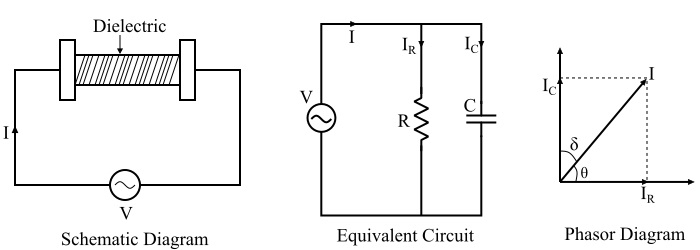
Refer the figure. There are two electrodes which are separated by a dielectric medium (it is the material to be heated) and a potential difference of high frequency is applied across the electrodes. This arrangement forms a capacitor. The phasor diagram of the equivalent circuit is also shown in the above figure. The capacitor formed in the arrangement for the dielectric heating may not be a pure capacitor, thus a resistor 'R' is also shown in parallel in circuit. However, the value of resistance 'R' is very high so that the current flowing though it is very small. For this reason, the capacitor current Ic can be considered equal to the total current I.
Mathematical Analysis
The mathematical expression of heat produced or power consumed in the dielectric heating method can be derived as follows −
Let
$$\mathrm{\mathrm{Power\: consume,}\:\mathit{P}\:=\:\mathit{VI\:cos\:\theta}}$$
Therefore, the total current in the circuit is given by,
$$\mathrm{\mathit{I}\:=\:\mathit{I_{\mathit{c}}}\:+\:\mathit{I_{\mathit{R}}}}$$
Though, the current IR is negligibly small, therefore can be neglected.
$$\mathrm{\therefore \mathit{I}\cong \:\mathit{I_{\mathit{c}}}}$$
$$\mathrm{\therefore\:\mathit{P} \:=\:\mathit{VI_{\mathit{c}}\:cos\:\theta s}}$$
$$\mathrm{\because \mathit{I_{\mathit{c}}\:=\:\frac{\mathit{V}}{\mathit{X_{\mathit{c}}}}\:\mathrm{and}\:\mathit{X_{\mathit{c}}\:=\:\frac{\mathrm{1}}{\mathrm{2}\pi \mathit{fC}}}}}$$
$$\mathrm{\Rightarrow \mathit{I_{\mathit{c}}}\:=\:\mathrm{2\pi \mathit{fCV}}}$$
$$\mathrm{\therefore \mathit{P}\:=\:\mathit{V}\mathrm{\left ( \mathrm{2\pi }\mathit{fCV} \right )}\:\mathrm{cos\:\theta}\:=\:\mathrm{2\pi }\mathit{fCV^{\mathrm{2}}}\:\mathrm{cos\:\theta}}$$
Where, the capacitance of a parallel plate capacitor is given by,
$$\mathrm{\mathit{C}\:=\:\frac{\epsilon _{\mathrm{0}}\epsilon _{\mathit{r}}\mathit{A}}{\mathit{t}}}$$
Where,
$\epsilon _{\mathrm{0}}$ is the permittivity of vacuum or air.
$\epsilon _{\mathit{r}} $is the relative permittivity of the dielectric material to be heated.
A is surface area of plates (electrodes).
t is the thickness of the material to be heated.
Refer the phasor diagram,
$$\mathrm{\mathit{\theta}\:=\:\mathrm{90^{\circ}}-\delta }$$
$$\mathrm{\Rightarrow \mathrm{cos\:\theta}\:=\:\mathrm{cos\mathrm{\left ( \mathrm{90^{\circ}}-\delta \right )}}\:=\:\mathrm{sin\:\delta }}$$
When δ is very small, then we have,
$$\mathrm{\mathrm{cos\:\theta}\:=\:\mathrm{sin\:\delta}\:=\:\delta }$$
$$\mathrm{\therefore \mathit{P}\:=\:\mathrm{2\pi \mathit{fCV^{\mathrm{2 }}\delta }}\:\mathrm{watts}}$$
This power is converted into heat in the dielectric heating. Here, the capacitance (C) and the angle δ shall be constant for a particular material to be heated.
Therefore,
$$\mathrm{\mathit{P}\propto \mathit{fV^{\mathrm{2}}}}$$
This is why, high voltage at high frequency is used for dielectric heating.
Advantages of Dielectric Heating
The advantages of the dielectric heating are given as follows −
With the dielectric heating, the heating of the material is uniform because the heat is produced within the material itself.
The process of heating can be made faster by increasing the frequency.
Dielectric heating is the only method for heating of non-conducting materials.
With the dielectric heating, the heating can be stopped immediately as and when required.
With this method, inflammable articles such as plastics, wooden products, etc. can be safely heated.

24K+ Views
