
Article Categories
- All Categories
-
 Data Structure
-
 Networking
-
 RDBMS
RDBMS
-
 Operating System
-
 Java
Java
-
 MS Excel
-
 iOS
iOS
-
 HTML
HTML
-
 CSS
CSS
-
 Android
-
 Python
-
 C Programming
-
 C++
C++
-
 C#
C#
-
 MongoDB
-
 MySQL
MySQL
-
 Javascript
-
 PHP
PHP
-
 Economics & Finance
Color Shades using RGB Led
To learn about RGB led and the difference between single-color LEDs, it is important to make a circuit using a microcontroller such as ESP32 or Arduino and RGB led. Then it is important to manage that circuit using a program. There are some simulators available to make the beginner of IOT learn such concepts without even having the IOT devices available.
However, to get real results, using the circuit components and making the actual circuit is important. In this article, using two different examples, the way to use the RGB led is given. In example 1, the actual circuit using a breadboard, ESP32, RGB LED, resistors, and wires is made and the components are controlled using the C program made using the Arduino IDE. In example 2, the Wokwi simulator is used with Arduino microcontroller and an RGB led with red, green, and blue single colored leds.
RGB led is an LED that can show the mix of RGB colors and can produce shades. It has 4 pins and the longest one (2nd in number) is -ve. The first one is for red, the third one for green, and the fourth one for blue.
Example 1: Using an RGB led with ESP32
First the ciruit is made using breadboard, ESP32, one RGB LED, 3 resistors and some male-to-male wires. Arduino IDE is then needed to write the C program, compile it and then push it into ESP32 for its execution.
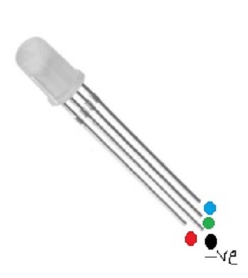
Fig: The RGB Led
So, first, make the circuit as shown in fig 1. Then write the C program using Arduino IDE.
Circuit Design Steps and Coding
Step 1 ? Connect the ESP32 microcontroller to the breadboard.
Step 2 ? Attach the breadboard negative rail to the ESP32?s GND.
Step 3 ? Use one RGB LED. Connect the longest leg of RGB LED to the blue rail directly and the other lines to resistors. Now connect the resistor pins to ESP32 pins (D21, D19, D18 ).
Step 4 ? Download Arduino IDE if it is not installed on the Computer and set it ups.
Step 5 ? Start Arduino IDE. Write the C program and compile it using the tick sign.
Step 6 ? Upload the program to ESP32 by pressing the right arrow near the tick sign. Check the results on the circuit.
The Code
#define LED_RED 18
#define LED_GREEN 19
#define LED_BLUE 21

#define RED_channel 0
#define GREEN_channel 1
#define BLUE_channel 2

#define PulseWM_Frequency 5000 // PulseWM frequency
#define PulseWM_resolution 8 // 8 bit resolution

void setup() {
   ledcAttachPin(LED_RED, RED_channel);
   ledcAttachPin(LED_GREEN, GREEN_channel);
   ledcAttachPin(LED_BLUE, BLUE_channel);

   ledcSetup(RED_channel, PulseWM_Frequency, PulseWM_resolution);
   ledcSetup(GREEN_channel, PulseWM_Frequency, PulseWM_resolution);
   ledcSetup(BLUE_channel, PulseWM_Frequency, PulseWM_resolution);
}

void loop() {
   RGB_Color(255, 5, 5); //Showing the shade of RED color
   delay(500);
   RGB_Color(20, 255, 4); //Showing the shade of green color
   delay(500);
   RGB_Color(10, 0, 255); //Showing the shade of blue color
   delay(500);
   RGB_Color(255, 255, 10); //Showing the shade of yellow color
   delay(500);
   RGB_Color(19, 255, 255); //Showing the shade of cyan color
   delay(500);
   RGB_Color(255, 50, 255); //Showing the shade of magenta color
   delay(500);
   RGB_Color(255, 20, 147); //Showing the shade of deep pink color
   delay(500);
   RGB_Color(255, 40, 40); //Showing the shade of deep pink color
}
void RGB_Color(int i, int j, int k){
   ledcWrite(RED_channel, i);
   ledcWrite(GREEN_channel, j);
   ledcWrite(BLUE_channel, k);
}
Viewing The Result - Example 1
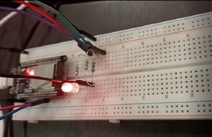
Fig 1: The actual circuit needed for the program and the result showing different colors and shades on RGB led
Example 2: Using RGB led with ArduinoUno on Wokwi
Wokwi is an online place where virtual circuits can be made and programs to control these circuits can be written and then the results can be tested. It is an easy to use and free service to start with learning IOT. The wokwi link is given here -
Wokwi Link: https://wokwi.com/
After login into wokwi, Use an Arduino Uno Project.
First, make the circuit in the right side area and write the code using C language in the left side code area as shown in the fig no.2
Circuit Design Steps and Coding
Step 1 ? Login to Wokwi. Start a new ArduinoUno project on Wokwi Simulator.
Step 2 ? Put an RGB led on the virtual circuit area using the + sign.
Step 3 ? Attach the longest leg of RGB Led to Uno?s GND.
Step 4 ? Use three red, green, and blue LEDs. Connect the smaller legs of LEDs to Uno's GND and the other lines to Uno pins (3, 5, 6)
Step 5 ? Assuming that the second leg of the LED is the longest (-ve ), connect the first pin of RGB to the red-led positive line, the third pin to the green led the positive line, and the fourth pin to the blue-led positive line, as shown in Fig 2.
Step 6 ? Write the C program using the Wokwi code area on the left.
Step 7 ? Compile the program using the play button on Wokwi. Check the results.
The Code
//Showing the shades of RGB and R, G, B LED demo
const int pinRedCol = 3;
const int pinGreenCol = 5;
const int pinBlueCol = 6;

void setup() {
   pinMode(pinRedCol, OUTPUT);
   pinMode(pinGreenCol, OUTPUT);
   pinMode(pinBlueCol, OUTPUT);
}

void loop() {
   RGB_Color(255, 5, 5); //Showing the shade of RED color
   delay(500);
   RGB_Color(20, 255, 4); //Showing the shade of green color
   delay(500);
   RGB_Color(10, 0, 255); //Showing the shade of blue color
   delay(500);
   RGB_Color(255, 255, 10); //Showing the shade of yellow color
   delay(500);
   RGB_Color(19, 255, 255); //Showing the shade of cyan color
   delay(500);
   RGB_Color(255, 50, 255); //Showing the shade of magenta color
   delay(500);
   RGB_Color(255, 20, 147); //Showing the shade of deep pink color
   delay(500);
   RGB_Color(255, 40, 40); //Showing the shade of deep pink color
}
void RGB_Color(int i, int j, int k){
   analogWrite(pinRedCol, i);
   analogWrite(pinGreenCol, j);
   analogWrite(pinBlueCol, k);
}
Viewing The Result
The program is compiled and the result can be seen as soon as the play button is pressed on Wokwi.
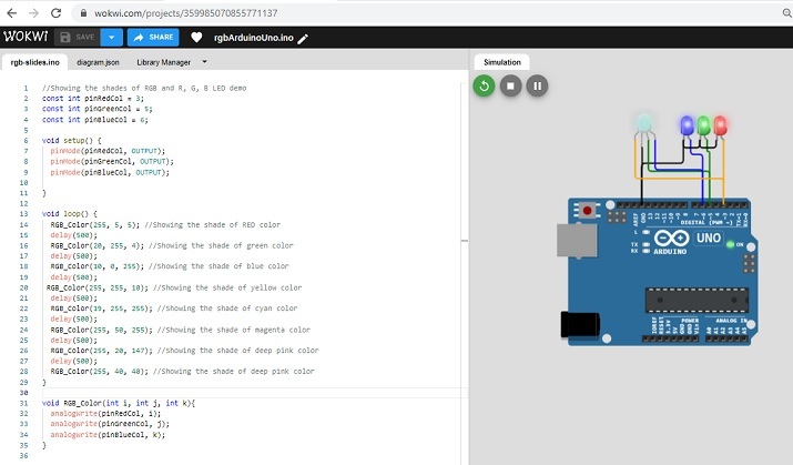
Fig 2: The circuit diagram on Wokwi and result showing colors and shades on RGB leds and single colored leds.
In this article, the way to use RGB led is shown. The first example shows the actual circuit using RGB led with ESP32 microcontroller. Another example is given to demonstrate the color mixing while using RGB led with ArduinoUno on Wokwi.

740 Views
