
Article Categories
- All Categories
-
 Data Structure
-
 Networking
-
 RDBMS
RDBMS
-
 Operating System
-
 Java
Java
-
 MS Excel
-
 iOS
iOS
-
 HTML
HTML
-
 CSS
CSS
-
 Android
-
 Python
-
 C Programming
-
 C++
C++
-
 C#
C#
-
 MongoDB
-
 MySQL
MySQL
-
 Javascript
-
 PHP
PHP
-
 Economics & Finance
Cascading of Decoders
What is a Decoder?
A decoder is a combinational logic circuit that converts an N-bit binary input code into a 2N output lines such that only one output line will be active for each one of the possible combinations of inputs. The block diagram of a decoder is shown in Figure-1.
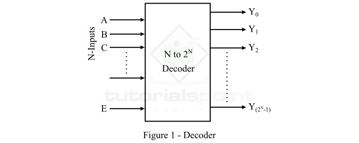
Here, A, B, C, etc. are the input lines, Y0, Y1, Y2,? etc. are the output lines, and E is the enable input of the decoder.
In this article, we will discuss cascading of decoders. Cascading of Decoders means the process of realizing a higher order decoder by connecting low order decoders together.
For example, we can obtain a 4 line to 16 line decoder by cascading two 3 line to 8 line decoders. Here, we will understand cascading of decoders with the help the following two examples ?
Cascading of 2 Line to 4 Line Decoders to Obtain a 3 Line to 8 Line Decoder.
Cascading of 3 Line to 8 Line Decoders to Obtain a 4 Line to 16 Line Decoder.
But before going into the cascading part, let us first known a bit about 2-to-4 line decoder, 3- to-8 line decoder, and 4-to-16 line decoder individually.
2-to-4 Decoder
A 2-to-4 decoder is a decoder circuit which has 2 input lines and 4 (22) output lines. The block diagram of a 2-to-4 decoder is shown in Figure-2 below.
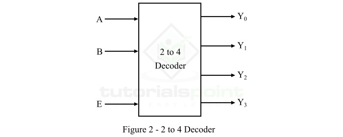
Here, A and B are the two inputs and Y0, Y1, Y2, and Y3 are the four outputs. One of these four output lines will be active for each combination of inputs when enable input E is active.
3-to-8 Decoder
A 3-to-8 decoder is a decoder circuit which has 3 input lines and 8 (23) output lines. The block diagram of a 3-to-8 decoder is shown in Figure-3.
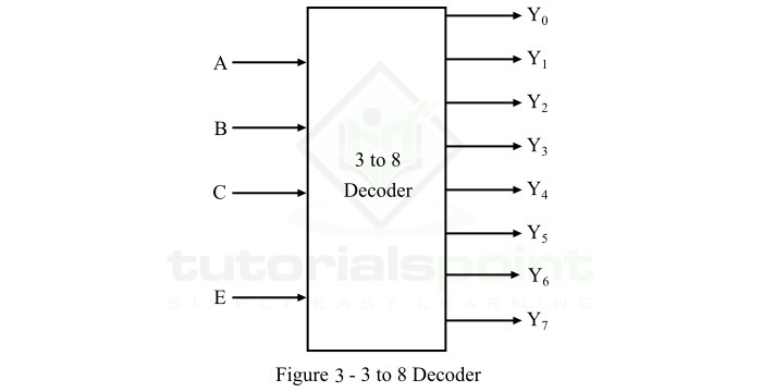
Here, A, B, and C are the three inputs and Y0, Y1, Y2, Y3, Y4, Y5, Y6, and Y7 are the eight outputs. One of these eight output lines will be active for each combination of inputs when enable input E is active.
4-to-16 Decoder
A 4-to-16 decoder is a decoder circuit which has 4 input lines and 16 (24) output lines. The block diagram of a 4-to-16 decoder is shown in Figure-4.
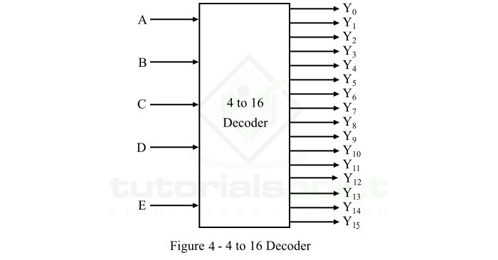
Here, A, B, C, and D are the three inputs and Y0, Y1, Y2, Y3, Y4,?Y15, are the sixteen outputs. One of these sixteen output lines will be active for each combination of inputs when enable input E is active.
Now, let us discuss the cascading of smaller decoders to get a larger decoder.
Cascading of 2-to-4 Decoders to Obtain a 3-to-8 Decoder
In this section, we will understand the implementation of a 3-to-8 lines decoder by cascading 2-to-4 line decoders.
As we already mentioned above that a 2-to-4 decoder consists of two input lines A and B, and four output lines Y0 to Y3. On the other hand, a 3-to-8 decoder has three input lines from A, B, and C and eight output lines from Y0 to Y7.
Hence, the number of lower order decoders that are to be cascaded to obtain a higher order decoder can be determined by using the following formula,
$$ \mathrm{Number\: of\: Lower\: Order\: Decoders\, =\, \frac{Number\: of\: outputs\: of\: higher\: order\: decoder}{Number\: of\: outputs\: of\: lower\: order\: decoder}}$$
In our case, number of outputs of lower order decoder is 4 and the number of higher order decoders is 8. Therefore,
$$\mathrm{Number\: of\: 2 - to - 4\: Decoders\, =\, \frac{8}{4}\, =\, 2}$$
Hence, we need to cascade two 2-to-4 line decoders to implement a 3-to-8 line decoder. The logic block diagram of a 3-to-8 line decoder obtained by cascading 2-to-4 line decoders is shown in Figure-5.
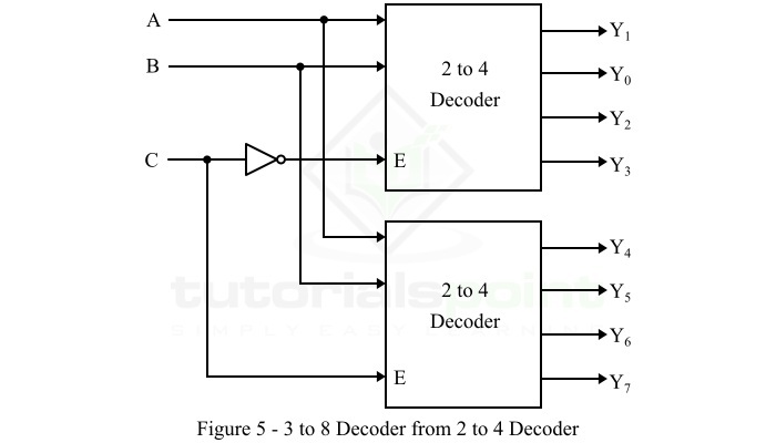
Here, the inputs A and B are applied to each 2-to-4 decoder in parallel. The complement of input C is connected to enable input E of the upper 2-to-4 decoder in order to get output, Y0 to Y3. The input C is direct connected to the enable input E of the lower 2-to-4 decoder to get the outputs, Y4 to Y7.
Cascading of 3-to-8 Decoders to Obtain a 4-to-16 Decoder
In this section, we will discuss the cascading of 3-to-8 decoders to implement a 4-to-16 decoder. As we know, a 3-to-8 decoder has three inputs A, B, and C, and eight outputs, Y0 to Y7. On the other hand, a 4-to-16 decoder has four inputs A, B, C, and D, and sixteen outputs, Y0 to Y15.
Hence, the number of 3-to-8 decoders to be cascaded to obtain a 4-to-16 decoder is given by,
$$\mathrm{Number\: of\: 3 - to - 8\: Decoders\, =\, \frac{16}{8}\, =\, 2}$$
Hence, two 3-to-8 decoders are to be cascaded to obtain a 4-to-16 decoder.
The logic block diagram of the 4-to-16 decoder obtained by cascading two 3-to-8 decoders is shown in Figure-6.
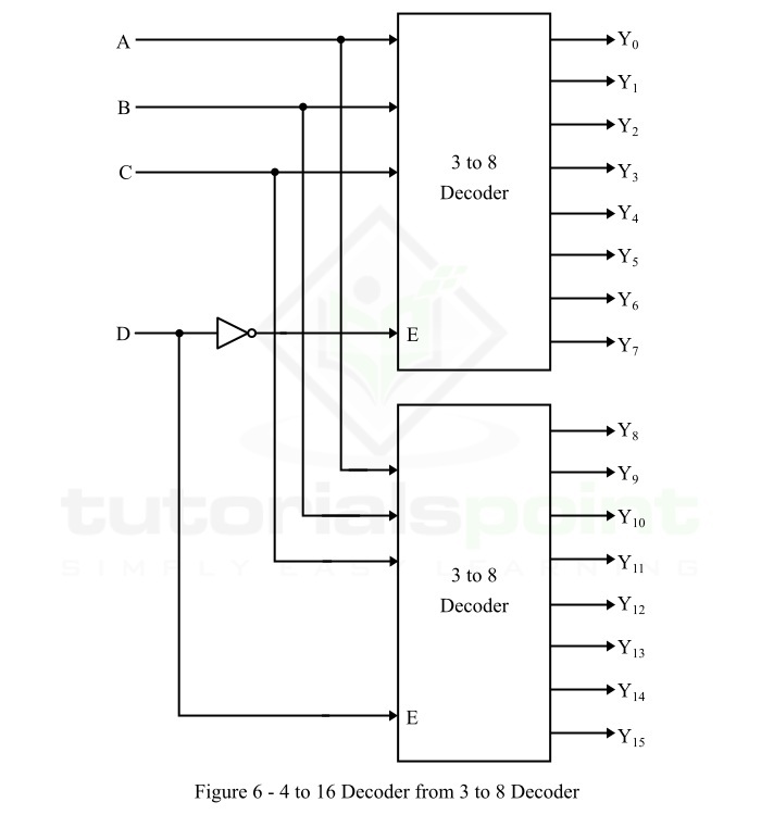
Here, the inputs A, B, and C are connected to each 3-to-8 decoder in parallel. The complement of fourth input D is connected to the enable input E of the upper 3-to-8 decoder to get the outputs, Y0 to Y7. The input D is directly applied to enable input E of the lower 3-to-8 decoder to get the outputs, Y8 to Y15.
This is how we can implement a higher-order decoder by cascading a set of lower-order decoder.

4K+ Views
