- Smart Grid - Home
- Smart Grid Introduction
- What is an Electric Grid?
- Electric Grid Evolution
- What is a Smart Grid?
- Smart Grid - Functions
- Smart Grid - Characteristics
- Smart Grid - Advantages
- Smart Grid - Components
- Smart Grid - Challenges
- Smart Grid Technologies
- Smart Energy Resources
- Power System Automation
- Smart Substations
- Substation Automation
- Smart Grid - Feeder Automation
- Energy Management System
- Smart Grid - FACTS
- HVDC Transmission
- Wide Area Monitoring
- SCADA in Smart Grid
- Smart Grid - DMS
- Smart Grid - OMS
- Volt/VAR Control
- Smart Grid - FMSR
- Smart Grid - HEDT
- Phase Shifting Transformers
- Smart Grid - PHEV
- Advanced Metering Infrastructure
- Smart Meters - Introduction
- Smart Meters - AMI
- Smart Meters - AMIS
- Communication Architecture
- Drivers & Benefits
- Phasor Measurement Unit
- Intelligent Electronic Devices
- Power Quality Management
- Power Quality in Smart Grid
- Power Quality Issues
- Power Quality Monitoring Techniques
- Power Quality Conditioners
- Electromagnetic Compatibility (EMC)
- Power Quality Audit
- Smart Grid Communication
- Smart Grid Communication
- Communication Network
- Communication Technologies
- Broadband Over Power Line
- Internet Protocols
- Web Services in Smart Grid
- Cloud Computing
- Multi Agent System Technology
- IP Based Protocols
- Cyber Security
Flexible AC Transmission System (FACTS)
One of the basic functions of an electric grid is to maintain a power balance in the network. It means the amount of power generated at any point of time must be equal to the amount of power consumed. This can be achieved through a highly efficient transmission system.
In a smart grid, there are several different types of transmission systems like FACTS, HVDC, etc. that are used for optimization of energy flow. In this chapter, we will explain the basics of FACTS (Flexible AC Transmission System) and its advantages.
What is Flexible AC Transmission System (FACTS)?
In electric grid, FACTS stands for Flexible AC Transmission System. FACTS is a transmission system that consists of static controllers for improving controllability and increasing the power transfer capability of the transmission network.
FACTS is basically a power electronic based transmission system. These power electronic components or devices provide capabilities to control one or more parameters of the AC transmission system to enhance its controllability and power transfer capacity.
Therefore, we can say that the primary aim of FACTS is to manage and optimize the operation of the AC transmission network. It enhances the efficiency, reliability, and functionality of the power network.
Importance of Flexible AC Transmission System
The reactive power compensation is one of the biggest problems in achieving most efficient and economical power transmission. In smart grid, there are well known devices called FACTS devices which are used for precise compensation of reactive power. These devices offer dynamically controlled compensation of reactive power by combining series and shunt compensation together.
To understand the important of FACTS technology, we first need to understand the power transfer capability of an AC system which is explained below.
Power Transfer Capability of AC System
Consider a typical loss-less AC transmission system as shown in the following figure.
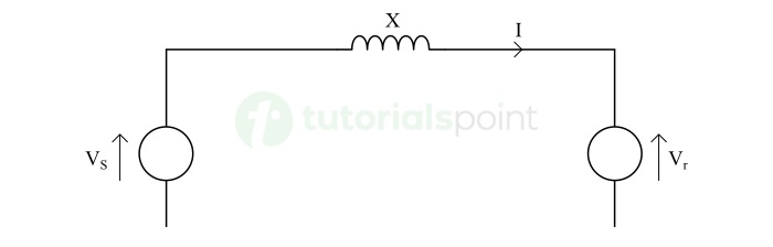
In this system,
$$\mathrm{V_{s} \: = \: Sending \: end \: voltage}$$
$$\mathrm{V_{r} \: = \: Receiving \: end \: voltage}$$
$$\mathrm{I \: = \: Line \: current}$$
$$\mathrm{X \: = \: Reactance \: of \: transmission \: line}$$
Since, we have considered a loss-less transmission system, hence the sending-end and receiving-end voltages are the same i.e.,
$$\mathrm{V_{s} \: = \: V_{r} \: = \: V(say)}$$
There is a phase lag of in the transmission line current and voltage which depends on the reactance of the transmission line X. Thus, the sending end and receiving end voltages can be given by,
$$\mathrm{V_{s} \: = \: V \: \cos(\frac{\delta}{2}) \: + \: jV \: \sin(\frac{\delta}{2})}$$
$$\mathrm{V_{r} \: = \: V \: \cos(\frac{\delta}{2}) \: − \: jV \: \sin(\frac{\delta}{2})}$$
Thus, the transmission line current will be,
$$\mathrm{I \: = \: \frac{V_{s} \: - \: V_{r}}{jX}}$$
$$\mathrm{\Rightarrow \: I \: = \: \frac{V \: \cos(\frac{\delta}{2}) \: + \: jV \: \sin(\frac{\delta}{2}) \: - \: V \: \cos(\frac{\delta}{2}) \: + \: jV \: \sin(\frac{\delta}{2})}{X} \: = \: \frac{2V \sin(\frac{\delta}{2})}{X}}$$
Again, the transmission line is a loss-less line. Thus, the active power P at any point of the line is the same i.e.,
$$\mathrm{P_{s} \: = \: P_{r} \: = \: P \: = \: VI \cos(\frac{\delta}{2})}$$
$$\mathrm{\Rightarrow \: P \: = \: V \cos(\frac{\delta}{2}) \: \cdot \: \frac{2V \sin(\frac{\delta}{2})}{X} \: = \: \frac{V^{2} \sin\delta}{X}}$$
Also, the reactive power at the sending end is opposite to that at the receiving end and equal, i.e.,
$$\mathrm{Q_{s} \: = \: -Q_{r} \: = \: Q \: = \: VI \sin(\frac{\delta}{2})}$$
$$\mathrm{Q \: = \: V \sin(\frac{\delta}{2}) \: \cdot \: \frac{2V \sin(\frac{\delta}{2})}{X} \: = \: \frac{V^{2} (1 \: - \: \cos\delta)}{X}}$$
As the phase angle δ is very small. Hence, the active power depends on δ, while the reactive power depends on the magnitude of voltage. Hence, we should have a grip control on the voltage to control the reactive power flow in the power lines.
Types of Flexible AC Transmission System Technologies
FACTS devices use the following three types of technologies to improve the controllability and power transfer capability of an AC transmission system. They are −
- Series Compensation − In series compensation, the line impedance X is decreased to increase the transmittable active power.
- Shunt Compensation − In shunt compensation, reactive power is injected into the transmission line to control the voltage magnitude.
- Combined Compensation − In combined compensation, both series and shunt technologies are combined together to provide a comprehensive control over power flow through the transmission line.
Types of Flexible AC Transmission System Devices
According to the type of compensation technology used, FACTS devices can be classified into the following major types −
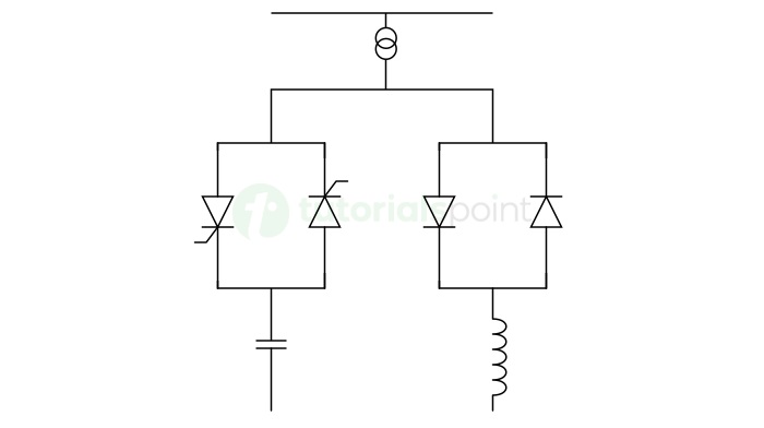
Static VAR Compensator (SVC)
SVC is a FACTS device used to control the voltage of transmission line by generating or absorbing the reactive power. It uses shunt compensation technology. The output of an SVC is adjusted by controlling the inductive or capacitive current. The circuit diagram of SVC is shown in the following figure.
Static Synchronous Compensator (STATCOM)
STATCOM is also a shunt compensation-based FACTS device. It is similar to SVC but it can provide faster and more precise control over the reactive power flow.
The unique feature of STATCOM is that its capacitive and inductive output currents can be controlled independently. Therefore, it can operate in both inductive and capacitive regions. The circuit diagram of a STATCOM device is shown in the following figure.
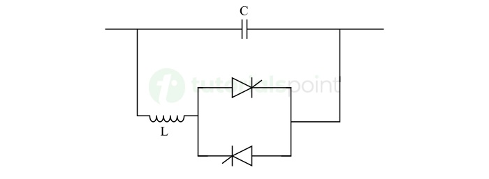
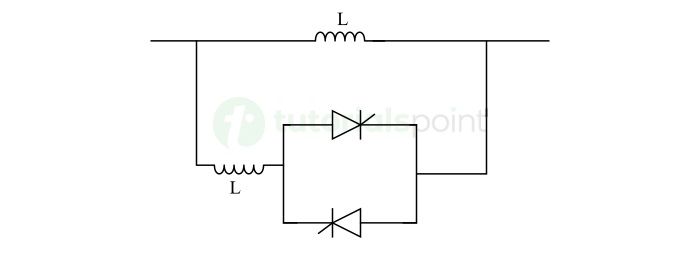
Thyristor Controlled Series Capacitor (TCSC)
TCSC is a FACTS device that consists of a series capacitor bank which is connected in parallel with a thyristor-controlled reactor. It is used to provide a smoothly variable series capacitive reactance to modify the equivalent reactance of the transmission line and control the power flow. The following figure depicts the circuit diagram of TCSC.
Thyristor Switched Series Capacitor (TSSC)
TSSC is a series compensation FACTS device that consists of a series capacitor bank which is connected in parallel with a thyristor switched reactor. The reactor provides a stepwise control of series capacitive reactance in the transmission line. The circuit diagram of TSSC is shown below −

Thyristor Controlled Series Reactor (TCSR)
TCSR is a series compensation FACTS device that provides a smoothly variable inductive reactance. It consists of a series inductor in parallel with a thyristor-controlled reactor as shown in the following figure −
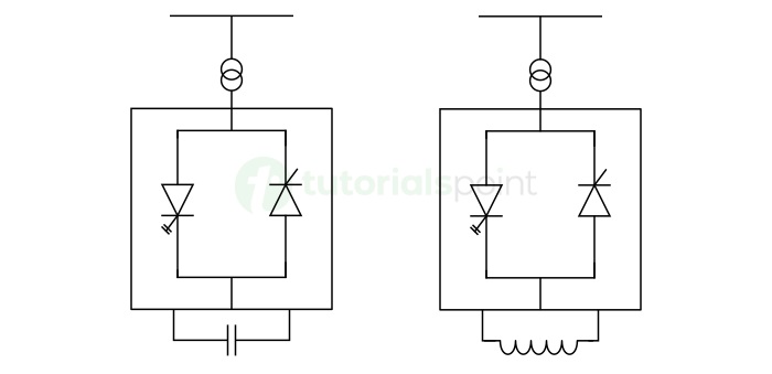
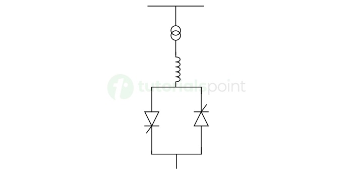
Thyristor Controlled Reactor (TCR)
In this type of FACTs device, the reactor is connected in series with the thyristor value. Where, the thyristor valve is made by joining two thyristors in anti-parallel configuration.
The TCR is a commonly used device in extra-high voltage transmission lines for reactive power compensation during no-load or light load conditions. The circuit diagram of a thyristor-controlled reactor is shown in the following figure −
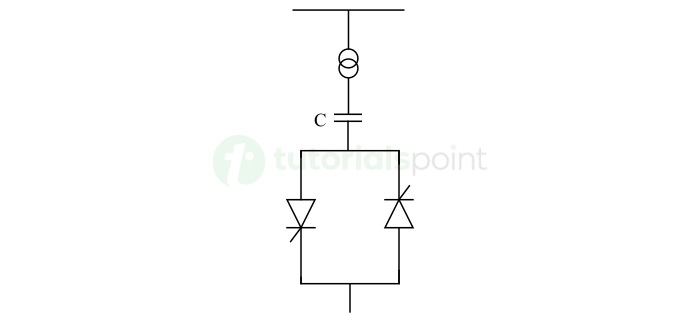
Thyristor Switched Capacitor (TSC)
TSC is a FACTS device that is also used in extra-high voltage transmission lines. But it is used during heavy load conditions to meet the reactive power demand. The circuit diagram of TSC is depicted in the following figure −
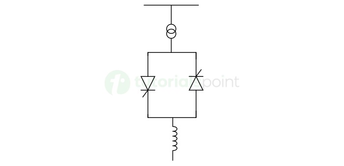
Thyristor Switched Reactor (TSR)
TSR is another reactor-based FACTS device which is similar to thyristor-controlled reactor (TCR). But it can operate in either zero or fully conditions and its equivalent reactance can vary in stepwise manner. The circuit diagram of the TSR is shown below −
Static Synchronous Series Compensator (SSSC)
SSSC is also a type of series compensation FACTS device. It consists of a voltage source converter connected in series with the transmission line through a transformer. The most important feature of the SSSC is that it can operate as a controllable series capacitor and a series inductor and its injected voltage is independent to the line intensity.

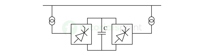
Unified Power Flow Controller (UPFC)
UPFC is a FACTS device that is a combination of STATCOM and SSSC which are combined together through a DC link. This FACTS device is capable in providing a bi-directional flow of real power between series output terminals of SSSC and shunt output terminals of STATCOM. Therefore, UPFC employs both series compensation and shunt compensation. The circuit diagram of UPFC is shown in the following figure −
Advantages of Flexible AC Transmission System Devices
The major advantages of FACTS devices are listed below −
- The use of FACTS devices in transmission lines increases their power transfer capability and reduce the needs for new transmission lines.
- FACTS devices also increase the loading capacity of the transmission lines.
- FACTS devices reduce the amount of reactive power in transmission lines and provides a way for transmitting high amount of real power to the loads.
- FACTS devices provide control over the power transmission and thus allow for power flow optimization.
- The use of FACTS devices in transmission line reduces the transmission cost and hence the energy cost.
- They stabilize the line parameters such as voltage, frequency, thermal factor, transients, etc. Hence, FACTS devices improve the power quality.
- FACTS technology is environment friendly because it does not contain any kind of environment threatening material.
- FACTS devices also improve the power factor of the transmission network.
- The use of FACTS devices in transmission lines also enhances the reliability and flexibility of the lines.
Disadvantages of Flexible AC Transmission System Devices
However, the use of FACTS devices in transmission network offers several benefits as listed above. But these devices result in some disadvantages as well.
Some of the common drawbacks of FACTS devices are listed below −
- In FACTS devices, power electronic switches are used to control the power flow in lines. These power electronic switches can introduce harmonics in the power supply. Therefore, we need to use active filters to remove these harmonics which adds extra cost.
- FACTS devices are expensive and increase the cost of transmission system.
- FACTS devices also have a certain limit of power transmission.
- A continuous maintenance is required for these FACTS devices which is a cost intensive task.
- There is also a certain amount of power loss inside the FACTS devices.
- Unexpected current spikes or fluctuations can damage the components of FACTS devices and their replacement is very expensive.
Conclusion
Flexible AC Transmission System (FACTS) is an advanced technology of power transmission developed to improve the reliability, stability, controllability, and efficiency of the transmission networks. FACTS devices are vital in the transmission networks which are subjected to smart grids.
The primary aim of using FACTS technology is to control the amount of reactive power flow in transmission lines and meet the energy demand with minimum number of transmission lines by enhancing the power transfer capacity through reactive power compensation.
